Supercharge Your Innovation With Domain-Expert AI Agents!

Remote power supply and distribution circuit for high-power DC voltage-stabilized power supply

A DC regulated power supply, power supply and distribution technology, applied in the direction of converting DC power input to DC power output, output power conversion devices, electrical components, etc. Reduce the problems of voltage fluctuation on the arrow, etc., to achieve the effect of stable operation, stable and controllable voltage, and satisfactory voltage regulation accuracy

Active Publication Date: 2017-04-26
BEIJING AEROSPACE AUTOMATIC CONTROL RES INST +1
View PDF3 Cites 0 Cited by
  • Summary
  • Abstract
  • Description
  • Claims
  • Application Information

AI Technical Summary

Problems solved by technology

[0002] During the ground test phase of the launch vehicle, a high-power DC stabilized power supply is used instead of the battery on the arrow to supply power for the equipment on the arrow to complete the system test. Since the ground power supply is placed in a safe place far from the power supply section of the rocket, its output is the same as that used on the arrow. There is a long distance between electrical equipment, which will cause a large voltage drop on the transmission path, which will reduce the voltage of the equipment on the arrow. At the same time, because the electrical load of the equipment on the arrow is in a fluctuating state, there will be a large voltage drop on the arrow. Fluctuations, especially during the power-on process will cause a large voltage drop, which will affect the safety of the equipment on the arrow
[0003] In order to solve this problem, the current launch vehicle has designed a remote acquisition feedback line in the ground power supply, and uses a relay to switch the feedback point. When the near end works, the feedback point is at the near end. When connecting the remote device power supply command, it needs to be connected. Connect the positive and negative lines of the feedback point to both ends of the remote load by switching the relay, so a separate control command is required when switching the voltage regulation point

Method used


Image

  • Remote power supply and distribution circuit for high-power DC voltage-stabilized power supply
  • Remote power supply and distribution circuit for high-power DC voltage-stabilized power supply
  • Remote power supply and distribution circuit for high-power DC voltage-stabilized power supply

Examples


Embodiment

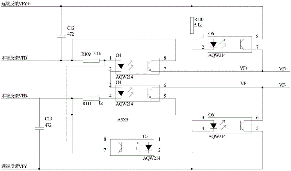
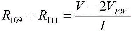
[0048] The power supply and distribution circuit of the present invention is used in the power supply and distribution system of a certain launch vehicle control system. The output voltage of the DC stabilized power supply is 28±5V, and the optocoupler relay is AQW214, which is a dual-channel optocoupler relay, and the turn-on current is 1.2mA. ; The forward voltage drop of the photodiode at the input end is about 1.25V, and the calculated values ​​of the resistors R109, R110, and R111 are 5.1kΩ, 5.1kΩ, and 1kΩ. This embodiment realizes automatic and seamless switching between the near end and the far end.


PUM


Abstract

Provided is a remote power supply and distribution circuit for a high-power DC voltage-stabilized power supply. A ground high-power DC voltage-stabilized power supply provides DC voltage to a far-end load on a rocket through a long-distance cable. When the far-end load is switched on, voltage at two ends of the far-end load is sent to the power supply for feedback through a seamless switching control circuit to ensure that power supply voltage of the far-end load meets requirements, and thus far-end voltage stabilization is realized. When the far-end load is not powered on, voltage of a local side is sent to the power supply for feedback through the seamless switching control circuit so that output voltage at the local side is stabilized. During switching between a power supplying state at the local side and a power supplying state of the far end, seamless automatic switching of a power supply feedback voltage stabilization line between the local side and the far end is realized through the seamless switching circuit. The switching control circuit is simple and reliable, enables automatic seamless switching to be realized between two states, needs no additional switching instructions and control logic, and helps to solve the problem of a conventional circuit that power supply output voltage tends to drop during switching.

Description

technical field [0001] The invention relates to a remote power supply and distribution circuit of a high-power DC stabilized power supply, which is applied to a system with long-distance DC remote power supply in the electrical system of a launch vehicle. Background technique [0002] During the ground test phase of the launch vehicle, a high-power DC stabilized power supply is used instead of the battery on the arrow to supply power for the equipment on the arrow to complete the system test. Since the ground power supply is placed in a safe place far from the power supply section of the rocket, its output is the same as that used on the arrow. There is a long distance between electrical equipment, which will cause a large voltage drop on the transmission path, which will reduce the voltage of the equipment on the arrow. At the same time, because the electrical load of the equipment on the arrow is in a fluctuating state, there will be a large voltage drop on the arrow. Fluc...

Claims


Application Information

Patent Timeline
IPC IPC(8): H02M3/156
CPCH02M3/156
Inventor 孙兆牛田建宇陈放王雨萌李学锋苏磊杨岫婷权赫张嗣锋刘畅
Owner BEIJING AEROSPACE AUTOMATIC CONTROL RES INST
Features
  • R&D
  • Intellectual Property
  • Life Sciences
  • Materials
  • Tech Scout
  • Unparalleled Data Quality
  • Higher Quality Content
  • 60% Fewer Hallucinations
Learn More