Multi-antenna MIMO system

A multi-antenna and antenna technology, applied in the field of multi-antenna MIMO systems, can solve problems such as power loss, lower cost performance of multi-antenna MIMO systems, and inability to obtain beam gain.

Active Publication Date: 2017-04-26
SHANGHAI HUAWEI TECH CO LTD
View PDF6 Cites 6 Cited by
  • Summary
  • Abstract
  • Description
  • Claims
  • Application Information

AI Technical Summary

Problems solved by technology

[0003] However, compared with the user-level narrow beam of the traffic channel, the control channel can only use a wide beam to achieve coverage, and cannot obtain beam gain
More importantly, when multi-column antennas synthesize wide beams in the horizontal plane, there is usually a power loss due to the unbalanced amplitude weight setting.
In the existing technology, the control channel adopts a wide beam without additional beam gain and has power loss, which makes the multi-antenna MIMO system need to adopt a design method of increasing module power in order to meet the needs of traditional cell coverage , while the traffic channel and control channel in the prior art use a set of common transceivers, increasing the power means increasing the hardware cost and implementation complexity of the module, and reducing the cost performance of the multi-antenna MIMO system
For example, the existing multi-antenna MIMO system generally adopts the design of high power (such as 160 watts) and multiple transceivers. The traffic channel and the control channel all use the same set of transceivers, such as 16 transceivers. The output power of each transceiver is exactly the same, for example, the output power of each transceiver needs to be changed from 1 watt or 2 watts to 10 watts, and increasing the power means an increase in module hardware cost and implementation complexity , therefore, the prior art reduces the cost performance of the multi-antenna MIMO system

Method used


Image

  • Multi-antenna MIMO system
  • Multi-antenna MIMO system
  • Multi-antenna MIMO system

Examples


Embodiment Construction

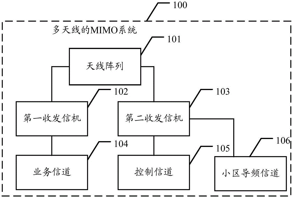
[0020] The embodiment of the present invention provides a multi-antenna MIMO system, which can not only realize narrow beam and low power of traffic channel, but also realize wide beam and high power of control channel, which not only improves system performance, but also ensures coverage, and at the same time The construction cost of the system is reduced.

[0021] Embodiments of the present invention will be described below in conjunction with the accompanying drawings.

[0022] The terms "first", "second" and the like in the description and claims of the present invention and the above drawings are used to distinguish similar objects, and are not necessarily used to describe a specific sequence or sequence. It should be understood that the terms used in this way can be interchanged under appropriate circumstances, and this is merely a description of the manner in which objects with the same attribute are described in the embodiments of the present invention. Furthermore, t...


PUM


Abstract

The invention discloses a multi-antenna MIMO system which can realize narrow beam and low power of a service channel and wide beam and high power of a control channel, improve system performance, guarantee coverage, and reduce system construction cost. The embodiment of the present invention provides a multi-antenna MIMO system comprising an antenna array, a first transceiver and a second transceiver, wherein the antenna array is connected to the first transceiver and the second transceiver, and the first transceiver is connected with the output port of the service channel, and the second transceiver is connected with the output port of the control channel and the output port of a cell pilot channel, the first transceiver comprises a first power amplifier, the second transceiver comprises a second power amplifier, the output power of the first power amplifier is less than that of the second power amplifier.

Description

technical field [0001] The present invention relates to the field of communication technology, in particular to a multi-antenna MIMO system. Background technique [0002] The traffic channel in the Multiple-Input Multiple-Output (MIMO) system with multiple antennas can bring array gain and space division multiplexing through user-level beamforming, so as to effectively increase the number of paired users, and further Improve spectral efficiency for performance gains. Wherein, the user-level beamforming refers to an antenna beam formed for a single user in a cell, which is different from the beamforming in which a cell control channel does not distinguish between users. [0003] However, compared with the user-level narrow beam of the traffic channel, the control channel can only use a wide beam to achieve coverage, and beam gain cannot be obtained. More importantly, when multi-column antennas synthesize wide beams in the horizontal plane, there will usually be power loss d...

Claims


Application Information

Patent Timeline
IPC IPC(8): H04B7/0413H04B7/0404
CPCH04B7/0404H04B7/0413Y02D30/70
Inventor 吕劲松蒲涛王健陈炜马霓陈鹏肖暄
Owner SHANGHAI HUAWEI TECH CO LTD
Why Eureka
Try Eureka