
Tube assembly and humidification system thereof

A humidification system and lamp technology, applied in air humidification systems, heating methods, electrical components, etc., can solve the problem of low thermal radiation efficiency of infrared light sources, and achieve the effect of improving light utilization.

Active Publication Date: 2017-04-26
GREE ELECTRIC APPLIANCES INC
View PDF2 Cites 6 Cited by
  • Summary
  • Abstract
  • Description
  • Claims
  • Application Information

AI Technical Summary

Problems solved by technology

[0005] The first technical problem to be solved by the present invention lies in the problem that the thermal radiation efficiency of the infrared light source in the prior art is not high, so a method that can improve the thermal radiation of the infrared light source is proposed Lamp assembly for efficiency and lamp life

Method used


Image

  • Tube assembly and humidification system thereof
  • Tube assembly and humidification system thereof
  • Tube assembly and humidification system thereof

Examples


Embodiment 1

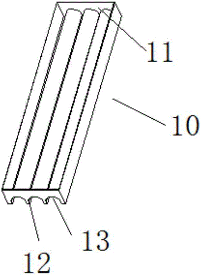
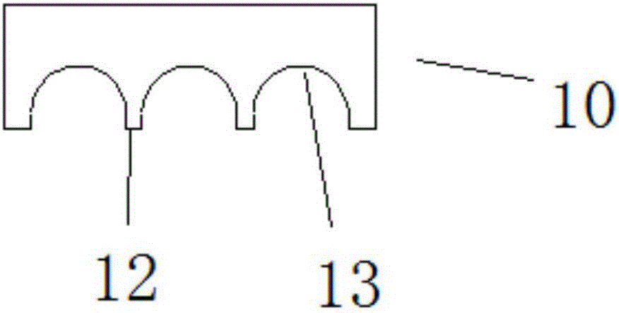
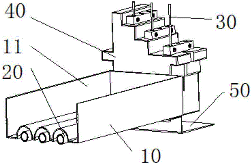
[0038] The lamp tube assembly of the humidifier provided in this embodiment includes: three infrared light sources, and a lampshade 10, such as image 3 As shown, the lampshade 10 is formed with three reflective spaces corresponding to the three infrared light sources independently on the side facing the infrared light source, that is, each infrared light source has an independent reflective space, and the inner surface of the reflective space is a reflective surface. Guide the light to a predetermined direction, so that the light emitted by each infrared light source can follow the ideal radiation path under the action of the reflective surface, and the heat radiation can effectively spread to the preset position (the water surface on the humidifier). Since each infrared light source has an independent reflective space, each infrared light source does not affect each other, which improves the light utilization rate of each infrared light source, and also avoids the heat radiat...

Embodiment 2

[0051] The humidification system provided in this embodiment includes: a humidification water tank 60 , and the lamp assembly as described in Embodiment 1 arranged above the humidification water tank 60 , so it has all the advantages of Embodiment 1. The lamp assembly cooperates with the humidifying water tank 60 to input cooling water into the humidifying water tank 60 as pre-heated water to increase the temperature of the water in the humidifying water tank 60 and further improve the humidification efficiency.

[0052] The liquid inlet of the liquid storage tank 11 communicates with the water inlet pipe 70 , and the external preheated water passes through the water inlet pipe 70 and the liquid inlet in turn to reach the liquid storage tank 11 and be heated. The liquid outlet is connected to the humidification water tank 60 through a water outlet pipe 80, such as Figure 4 As shown, the liquid outlet is located at the bottom of the liquid storage tank 11, and the liquid in th...


PUM


Abstract

The invention discloses a tube assembly and a humidification system thereof. The tube assembly comprises infrared light sources and a lampshade. At least two independently-arranged reflection spaces are formed to face one side of the infrared light sources. Each reflection space corresponds to one infrared light source. The interior surface of each reflection space is a reflection surface that guides light in a predetermined direction. Each infrared light source has one independently-arranged reflection space, so that light emitted from each infrared light source can effectively transmit to a preset position through heat radiation along an ideal radiation path transmission route under the effect of the reflection surface. The humidification system comprises a humidification water tank and a tube assembly disposed above the humidification water tank. The tube assembly and the humidification water tank cooperate with each other. Cooling water, taken as preheating water, is input to the humidification water tank to increase the water temperature of the water tank, so the humidification efficiency is improved.

Description

technical field [0001] The invention relates to a lamp tube assembly and a humidifying system with the lamp tube assembly, belonging to the technical field of electric appliances. Background technique [0002] Infrared humidifier is a kind of equipment used for humidification of air-conditioning system. Infrared rays are emitted by infrared halogen lamps, and the infrared rays are used to stimulate the vaporization of water molecules on the surface of the water tank to achieve humidification. It can quickly evaporate without boiling water and produce clean steam for use humidify. In order to improve the efficiency of energy utilization and prevent the infrared energy of the lamp tube from radiating to the surroundings, in the prior art, a lampshade is usually installed at the lamp tube, which is used to block the heat convection channel on the one hand, and to dissipate the scattered heat radiation on the other hand. Orient in the desired direction. Obviously, the desired ...

Claims


Application Information

Patent Timeline
Patent Type & Authority Applications(China)
IPC IPC(8): H05B3/00F24F6/10
CPCH05B3/0071F24F6/105
Inventor 王思许红吴凡黎汝令
Owner GREE ELECTRIC APPLIANCES INC
Learn More