A wrapped heat sink and an inductance efficient heat dissipation structure

A heat sink and cladding technology, which is applied in the field of high-efficiency heat dissipation structures of inductors, can solve problems such as low heat dissipation efficiency, inability to protect power devices such as inductors, water accumulation or dust accumulation in radiators, and achieve improved heat dissipation efficiency and good protection effects , the effect of increasing the contact area

Active Publication Date: 2019-09-17
KEHUA DATA CO LTD +1
View PDF11 Cites 0 Cited by
  • Summary
  • Abstract
  • Description
  • Claims
  • Application Information

AI Technical Summary

Problems solved by technology

For example, combiner boxes are used in solar photovoltaic power generation systems. In order to prevent the heat of power devices and inductors from interacting with each other, more and more combiner boxes change the inductance from built-in to external. However, combiner boxes are usually used in environments such as deserts. In relatively harsh places, the radiator needs to withstand the erosion of wind, sand and rain all year round. Due to the unreasonable structural design of the existing radiator, it is easy to accumulate water or dust on the surface of the radiator. Once the radiator fin is blocked, the heat dissipation effect will be reduced. Big discount
In addition, the radiator fins of the prior art radiators are unreasonably designed. The radiator fins located in the middle position, because the air flow will be blocked by the radiator fins on both sides, so it often cannot form convection well and becomes a blind area, and due to the heat accumulation problem , the heat sink in the middle tends to accumulate more heat; and the current heat sink cannot play a good guiding role in the airflow (natural wind or wind blown by the fan), resulting in that the airflow cannot circulate on the heat sink and bring The heat on the heat sink leads to low heat dissipation efficiency and cannot protect power devices such as inductors. The application of heat sinks has been greatly challenged.

Method used


Image

  • A wrapped heat sink and an inductance efficient heat dissipation structure
  • A wrapped heat sink and an inductance efficient heat dissipation structure
  • A wrapped heat sink and an inductance efficient heat dissipation structure

Examples


Embodiment Construction

[0033] In order to make the technical problems, technical solutions and beneficial effects to be solved by the present invention clearer and clearer, the present invention will be further described in detail below in conjunction with the accompanying drawings and embodiments. It should be understood that the specific embodiments described here are only used to explain the present invention, not to limit the present invention.

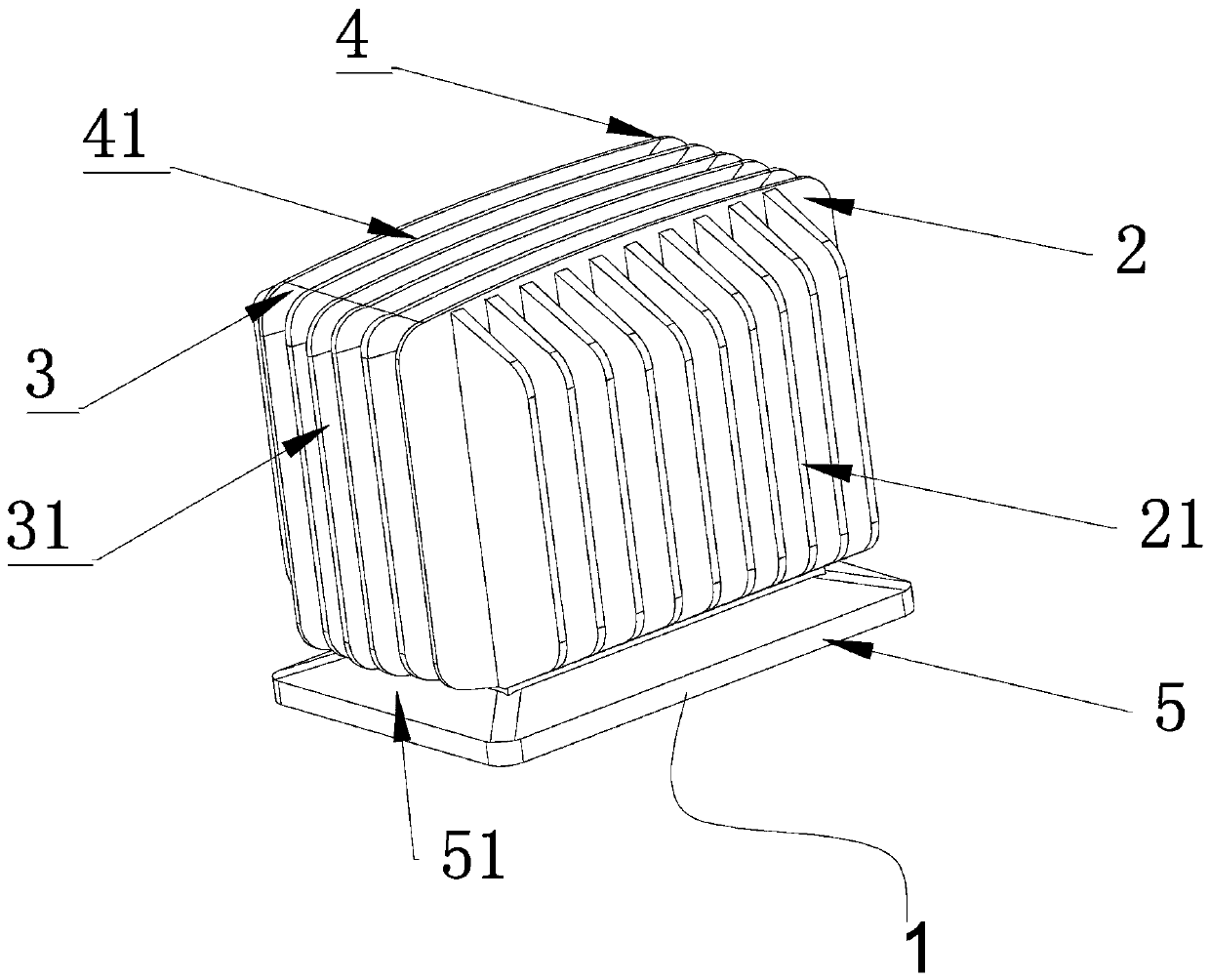
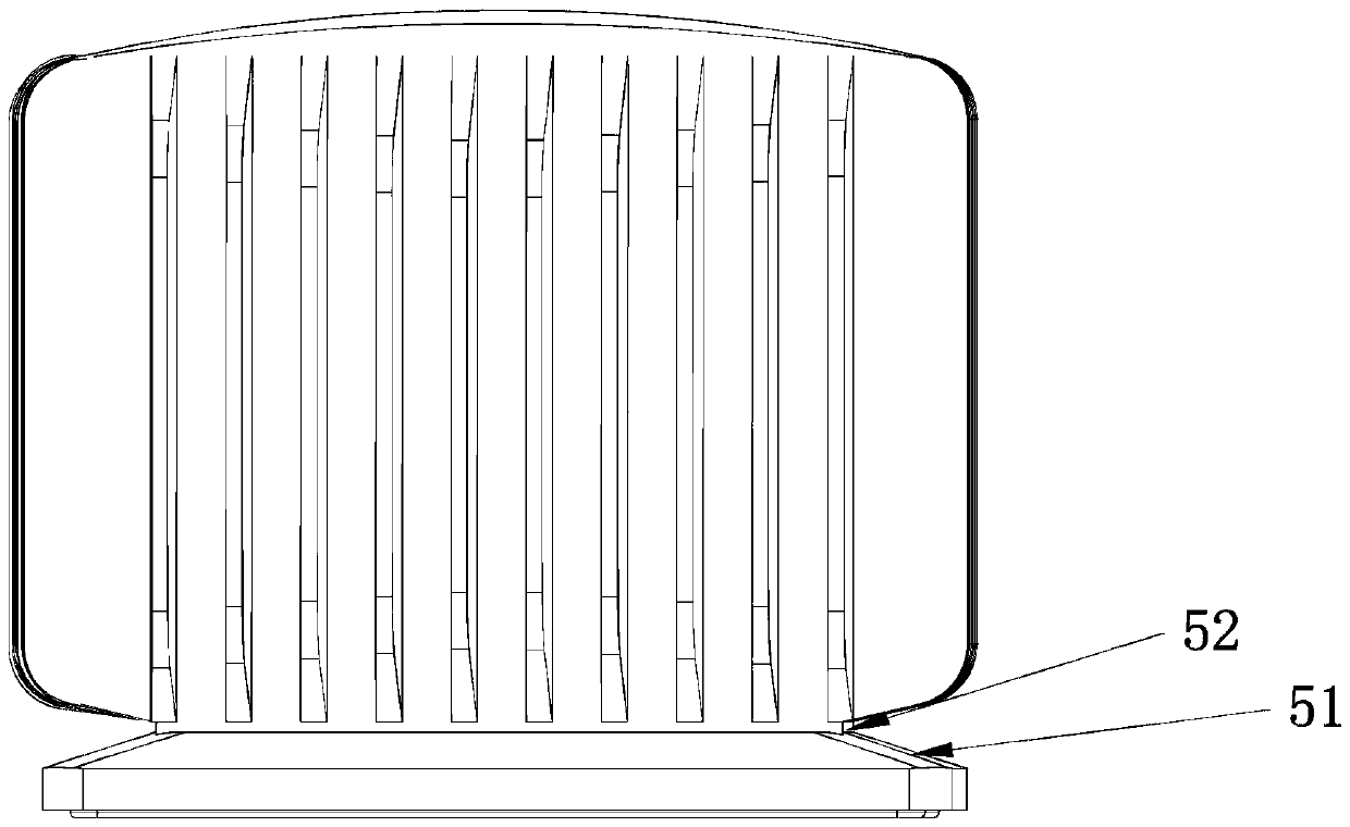
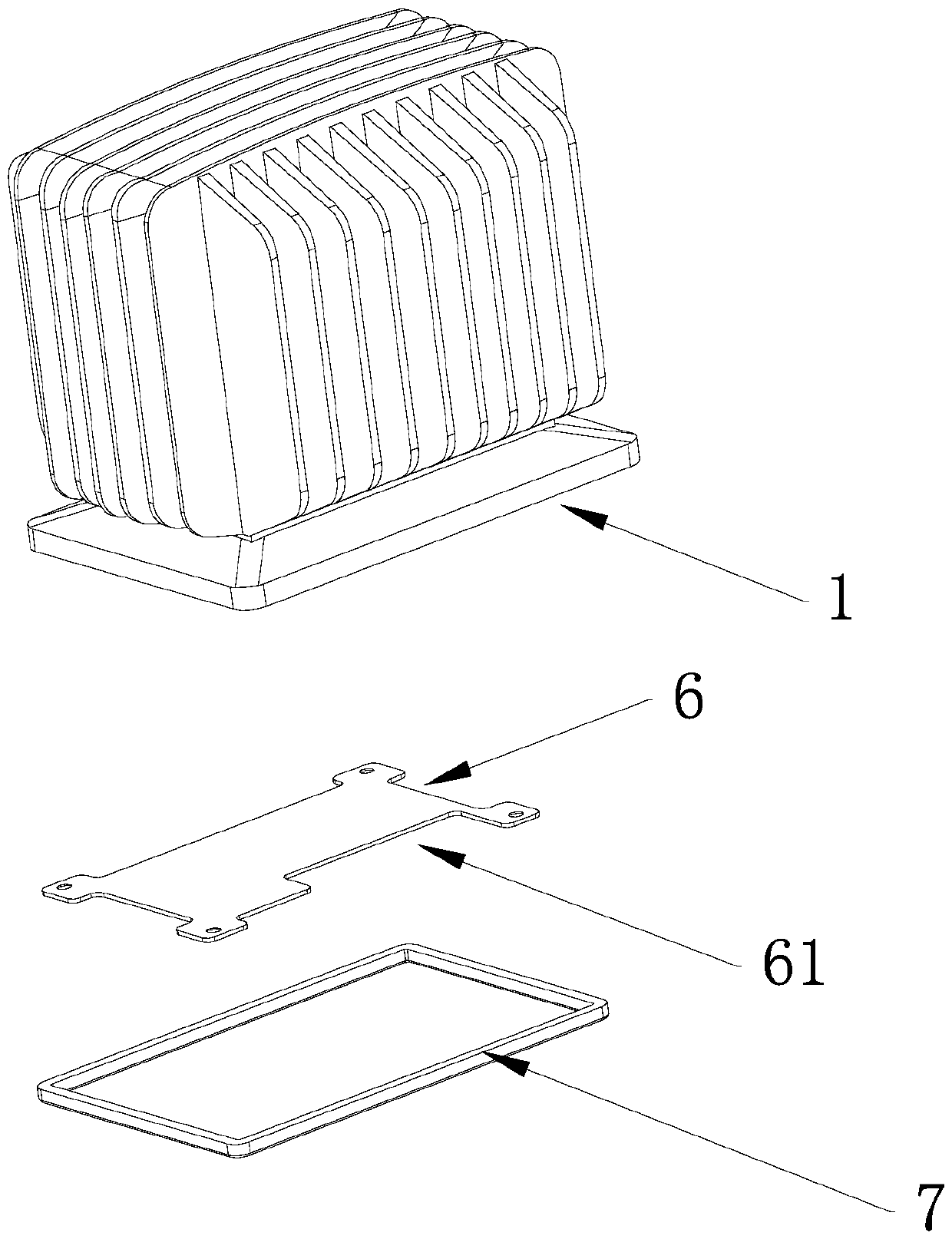
[0034] Such as figure 1 , figure 2 , image 3 and Figure 4As shown, a clad radiator includes a heat dissipation body 1, the heat dissipation body 1 includes a housing cavity, and the bottom of the housing cavity is provided with an opening for placing power supply components therein; the heat dissipation body includes a first outer wall 2, The second outer wall 3, the top wall 4, and the mounting seat 5 adjacent to the first outer wall 2 also include a plurality of first heat sinks 21, second heat sinks 31, third heat sinks 41, first heat sinks 21 ...


PUM


Abstract

The invention discloses a cladding type radiator and an inductive high-efficiency heat dissipation structure. The cladding type radiator comprises a heat dissipation main body, the heat dissipation main body comprises an accommodation cavity, and the bottom of the accommodation cavity is provided with an opening for placing an electrical appliance component therein. The cladding type radiator further comprises a plurality of first radiating fins, the heat dissipation main body comprises a first outer wall, the first radiating fins extend outwards in a mode of being vertical to the first outer wall, and along the direction vertical to the first radiating fins, the closer the first radiating fins are to the central portion of the direction, the heights extending outwards from the first outer wall are larger. The invention simultaneously provides an inductive high-efficiency heat dissipation structure using the cladding type radiator. The cladding type radiator and the inductive high-efficiency heat dissipation structure can be adapted to harsh environment, are high in protection grade and high in heat dissipation efficiency and can resist water accumulation and dust accumulation.

Description

technical field [0001] The invention relates to a heat sink and an inductor efficient heat dissipation structure, in particular to a wrap-type radiator with good heat dissipation performance and an inductor high-efficiency heat dissipation structure using the wrap-type radiator. Background technique [0002] With the rapid development of industrial technology, large-scale power electronic equipment is more and more widely used in various industries, and the power level and power density are also getting higher and higher, so the requirements for power electronic components are also getting higher and higher. For example, combiner boxes are used in solar photovoltaic power generation systems. In order to prevent the heat of power devices and inductors from interacting with each other, more and more combiner boxes change the inductance from built-in to external. However, combiner boxes are usually used in environments such as deserts. In relatively harsh places, the radiator n...

Claims


Application Information

Patent Timeline
Patent Type & Authority Patents(China)
IPC IPC(8): H05K7/20
Inventor 林艺成陈敏蔡德煌张炫东
Owner KEHUA DATA CO LTD
Why Eureka
Try Eureka