Upflow distributor and upflow reactor

A distributor and up-flow technology, which is applied to the field of up-flow distributors and up-flow reactors, can solve the problems of inability to provide stable and effective gas-liquid mixing, limited gas-liquid mixing effect, and influence on the gas phase dissolution rate.

Active Publication Date: 2017-05-03
CHINA PETROLEUM & CHEM CORP +1
View PDF8 Cites 2 Cited by
  • Summary
  • Abstract
  • Description
  • Claims
  • Application Information

AI Technical Summary

Problems solved by technology

The mixing performance of the logistics distribution device directly affects the dissolution rate of the gas phase in the liquid phase, which in turn affects the gas-liquid mass transfer efficiency in the reactor.
Although the upflow distributor in the prior art can achieve a certain gas-liquid mixing effect, due to structural limitations, its gas-liquid mixing effect is limited
[0004] The main problem in the upflow logistics distribution device in the prior art is that it cannot provide stable and effective gas-liquid interphase mixing, and the mass transfer efficiency between gas-liquid flows is low

Method used


Image

  • Upflow distributor and upflow reactor
  • Upflow distributor and upflow reactor
  • Upflow distributor and upflow reactor

Examples


Embodiment Construction

[0024] The specific embodiments of the present invention will be described in detail below. It should be understood that the specific embodiments described herein are only used to illustrate and explain the present invention, and not to limit the present invention.

[0025] In the present invention, if there is no explanation to the contrary, the location words used should be properly interpreted in combination with the context and the direction in actual use.

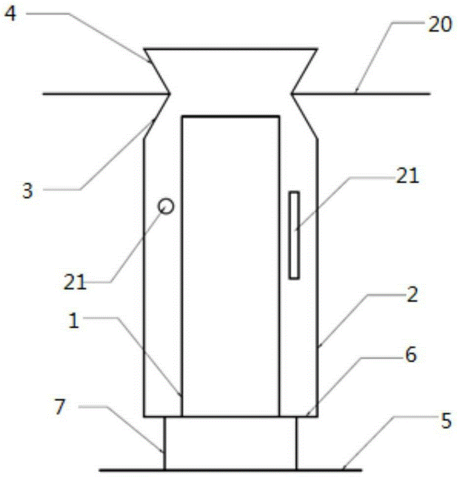
[0026] The present invention provides an upflow distributor, wherein the upflow distributor includes a main flow pipe 1, a gas flow pipe 2 and a mixing part 3, and a gas stream can be transmitted through the gas flow pipe 2. The main flow pipe 1 and the upper end of the gas guide tube 2 are both in communication with the mixing part 3.

[0027] The gas flow pipe 2 is used to transport gas, and the main flow pipe 1 is mainly used to transport liquid-based fluids. Among them, the fluid transmitted through the main flow tube 1...


PUM


Abstract

The invention relates to the field of petrochemical engineering and discloses an upflow distributor and an upflow reactor. The upflow distributor comprises a main flow guiding tube (1), a gas flow guiding tube (2) and a mixing part (3), wherein gas stream can be transmitted by the gas flow guiding tube (2); and the upper end orifices of the main flow guiding tube (1) and the gas flow guiding tube (2) both communicate with the mixing part (3). The gas flow guiding tube is mainly used for transmitting gas fluid separated from mixed fluid while the main flow guiding tube is used for transmitting the rest fluid which is mainly liquid fluid, and the fluids flowing through the main flow guiding tube and the gas flow guiding tube are mixed at the mixing part. By adoption of the technical scheme, the fluids flowing through the main flow guiding tube and the gas flow guiding tube reach the mixing part, and the mixing part enables gas and liquid in the mixed fluid to be better mixed.

Description

Technical field [0001] The present invention relates to the field of petrochemical industry, in particular to an upflow distributor and an upflow reactor. Background technique [0002] At present, in the petrochemical industry, upflow reactors are widely used, such as fixed bed flow hydrogenation reactors, distillate liquid phase hydrogenation reactors, suspended bed hydrogenation reactors, and fluidized bed hydrogenation reactors. Regardless of the upflow reactor, the gas-liquid stream needs to be evenly distributed to the interface of the catalyst bed to avoid the adverse effects of drift or channeling. [0003] In an upflow reactor, the gas and liquid flow upward at the same time. Generally, the liquid phase is the continuous phase and the gas phase is the dispersed phase. With the disturbance caused by the upward flow of the flow, the gas phase partially dissolved in the liquid phase will escape. Therefore, before entering the catalyst bed, a flow distribution device is requir...

Claims


Application Information

Patent Timeline
Patent Type & Authority Applications(China)
IPC IPC(8): B01J8/02
CPCB01J8/0242B01J8/0278B01J2208/00548B01J2208/02
Inventor 王璐璐毛俊义王少兵秦娅丁石
Owner CHINA PETROLEUM & CHEM CORP
Why Eureka
Try Eureka