Eureka AIR delivers breakthrough ideas for toughest innovation challenges, trusted by R&D personnel around the world.

Plasma exhaust gas purification device

A technology of waste gas purification and treatment device, which is applied in gas treatment, separation method, dispersed particle separation, etc., and can solve the problems of insufficient treatment, inability to be used repeatedly, and unsatisfactory treatment effect.

Pending Publication Date: 2017-05-10
河北乾昇节能科技发展有限公司
View PDF4 Cites 1 Cited by
  • Summary
  • Abstract
  • Description
  • Claims
  • Application Information

AI Technical Summary

Problems solved by technology

[0002] Existing equipment for waste gas purification treatment, chemical treatment equipment is relatively extensive, but after all, chemical treatment will produce a certain amount of other derivative substances, the treatment is not sufficient, and more raw materials are used in the process of chemical treatment of waste gas, and Most of them are substances that cannot be used repeatedly, and the waste is relatively large
At present, there are also equipment that use physical principles to purify waste gas, such as devices that use plasma to purify waste gas. These treatment devices are either immature in technology and unsatisfactory in treatment effect, or have single processing components in the equipment and low processing capacity, which cannot meet the requirements Large-scale equipment waste gas treatment use

Method used


Image

  • Plasma exhaust gas purification device
  • Plasma exhaust gas purification device

Examples


Embodiment Construction

[0019] The present invention will be further described below in conjunction with the accompanying drawings and embodiments.

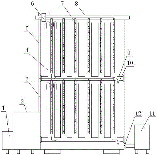
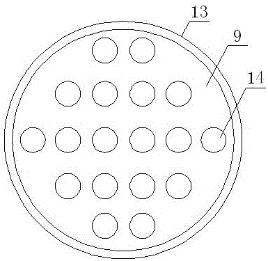
[0020] See attached Figure 1-2 The exhaust gas purification treatment device disclosed in the present invention is a plasma exhaust gas purification treatment device, which includes a power supply 1, a transformer 2, a box body 3, a gas channel 4, a motor wire 5, an air inlet 6, and an electrode rod 7 , Cover plate 8, clapboard 9, air outlet 10, induced draft fan 11, exhaust port 12, clapboard jacket 13, channel positioning hole 14. Among them, the power supply and the transformer work together, the power supply input is high voltage 1.5WV, and the output is low voltage 36V. The power supply is connected with the transformer, the output ends of the transformer are respectively connected with the motor wires, and the power supply and the transformer are respectively arranged outside the box body. The induced fan is arranged outside the other side of t...


PUM


Abstract

The invention discloses a plasma exhaust gas purification device. A cover plate is arranged at the top of a box, a partition is arranged in the middle of the box, the cover plate and the lower surface of the partition are provided with electrode bars, the partition is a hollow plate, a gas outlet is formed in the bottom surface of the partition, penetrated channel positioning holes are uniformly formed in the upper surface of the partition and vertically correspond to the electrode bars, gas channels are inserted into the channel positioning holes and sleeve the outside of the electrode bars, a power supply is connected with a transformer, output ends of the transformer are connected with motor leads respectively, the power supply and the transformer are respectively arranged on the outside of the box, and an induced draft fan is arranged on the outside of the other side of the box and communicated with the gas outlet in the bottom of the box through a connecting pipe. According to the device, the number and the scale of the electrode bars, the gas channels and the partition can be randomly increased according to actual treatment conditions, treatment capacity is random, treatment effect is obvious, exhaust gas is purified through physical action, and the purification device with fewer detrimental impurities is repeated and frequent to use.

Description

technical field [0001] The invention relates to a waste gas purification treatment device, in particular to a plasma waste gas purification treatment device. Background technique [0002] Existing equipment for waste gas purification treatment, chemical treatment equipment is relatively extensive, but after all, chemical treatment will produce a certain amount of other derivative substances, the treatment is not sufficient, and more raw materials are used in the process of chemical treatment of waste gas, and Most of them are substances that cannot be used repeatedly, and the waste is relatively large. At present, there are also equipment that use physical principles to purify waste gas, such as devices that use plasma to purify waste gas. These treatment devices are either immature in technology and unsatisfactory in treatment effect, or have single processing components in the equipment and low processing capacity, which cannot meet the requirements Used for large-scale e...

Claims


Application Information

Patent Timeline
IPC IPC(8): B01D53/32
CPCB01D53/32B01D2259/818
Inventor 康广民马建民霍成路
Owner 河北乾昇节能科技发展有限公司
Why Eureka
Eureka Blog
Learn More