Light stream vortex array based material distributed control platform and control method
A distributed control and control method technology, applied in chemical instruments and methods, laboratory containers, laboratory stools/lab benches, etc., can solve problems such as limited range of action, distributed capture of difficult materials, etc., to achieve application Wide range of occasions, low cost, and simple system architecture
- Summary
- Abstract
- Description
- Claims
- Application Information
AI Technical Summary
Problems solved by technology
Method used
Image
Examples
Embodiment 1
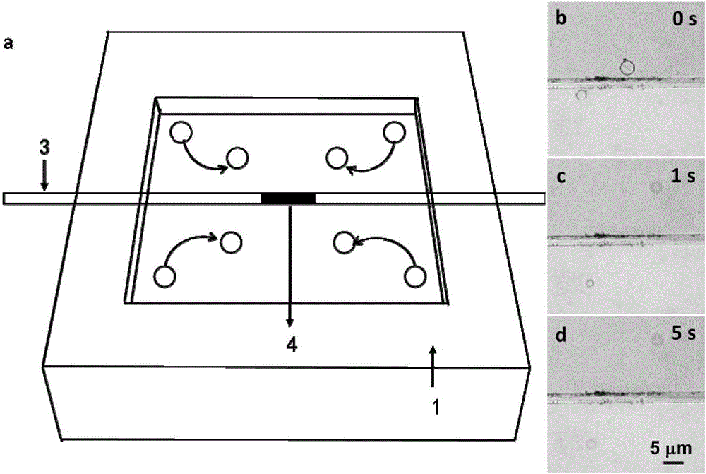
[0057] This embodiment shows a distributed optical flow capture technology based on an optical flow vortex array. Such as image 3 As shown in a, the micro-nano materials near the vortex will be affected by two forces. The first force is a viscous force and its direction is along the vortex flow direction. The second force is a lift force whose direction is perpendicular to the vortex flow direction and points to the vortex center. Under the action of viscous force and lift force, the micro-nano materials will enter the center of the vortex in a spiral trajectory. Therefore, the center of the vortex can be used as a stable point for capturing material. Magrini convection can provide four vortex centers, which means that four capture positions can be provided, thus realizing the distributed capture technology based on the optical flow vortex array. image 3 Shown in b-d is the overall process of vortex 1 and vortex 3 respectively capturing two polystyrene microspheres. At t=0s...
Embodiment 2
[0059] This embodiment shows an optical flow manipulation technique by tuning the power of a light source. Such as Figure 4 As shown in a, as the light input power increases, the photothermal heat source on the surface of the microfluid absorbs more light energy, releases more heat energy, and the temperature also increases. In this process, the microfluid spreads the thermal energy farther, so that the resulting Marangoni convection has a larger range and faster speed. The increase of the convection range affects the movement of the center of the vortex, and finally guides the capture material away from the light and heat source. Conversely, the reduction in power can also guide the capture material closer to the photothermal heat source. Figure 4 Shown in b-d is the experimental process of realizing optical flow control by tuning the light source power. Under the input power of 10mW, two polystyrene microspheres were captured by the vortex 2 and the vortex 4 and stopped at...
Embodiment 3
[0061] This embodiment shows the optical flow control technology by tuning the position of the photothermal heat source. Such as Figure 5 As shown in (a), under the control of the micro adjustment frame, the photothermal heat source moves from the old position to the new position on the surface of the microfluid. The disappearance of the photothermal heat source in the old position leads to the disappearance of Marangoni convection, while the new position The emergence of light and heat sources led to the emergence of Marangoni convection. In this process, the center of the vortex also moves from the old position to the new position, and finally guides the capture material to move from the old position to the new position. Figure 5 (b)-(d) shows the experimental process of realizing optical flow control by tuning the position of the photothermal heat source. When t=0s, under the input power of 10mW, four polystyrene microspheres are captured by the vortex 1-4 and stopped at t...
PUM
 Abstract
Description
Claims
Application Information
 - R&D
- Intellectual Property
- Life Sciences
- Materials
- Tech Scout
- Unparalleled Data Quality
- Higher Quality Content
- 60% Fewer Hallucinations
Browse by: Latest US Patents, China's latest patents, Technical Efficacy Thesaurus, Application Domain, Technology Topic, Popular Technical Reports.
© 2025 PatSnap. All rights reserved.Legal|Privacy policy|Modern Slavery Act Transparency Statement|Sitemap|About US| Contact US: help@patsnap.com


