Antenna structure and electronic equipment

An antenna structure and antenna technology, applied in antennas, antenna coupling, antenna arrays, etc., can solve the problems of increased external structural formula, decreased antenna performance, and shortened distance between antennas, so as to improve comprehensive competitiveness and reduce degradation degree, the effect of reducing the horizontal area

Active Publication Date: 2021-07-27
ETHETA COMM TECH SHENZHEN CO LTD
View PDF11 Cites 0 Cited by
  • Summary
  • Abstract
  • Description
  • Claims
  • Application Information

AI Technical Summary

Problems solved by technology

[0002] In the 5G (fifth-generation mobile communication) era, due to the need to meet the communication requirements of MIMO (multi-input and multi-output, that is, multiple input and multiple output) with more channels, and to cover more new frequency bands, the number of antennas in the mobile phone Compared with the previous generation of mobile communication, the number of mobile communication generations has increased significantly, but the size of the mobile phone has not increased proportionally, so the distance between the antennas has been significantly shortened, and the coupling phenomenon between antennas of the same frequency or non-same frequency has become more serious (especially the same frequency or near-frequency antennas), the performance of the antenna is significantly reduced, and the user's wireless communication experience is degraded
However, the layout method cannot be used well in a space-constrained and compact system, so the effect is often not significant. The external structural method will often increase the distance between antennas, which will affect the system compactness and even the system size. The defective ground method will destroy the system. Therefore, in the actual compact system, the feasibility is often low, and the artificial material method design is more complicated, and often requires additional space or carrier, and the circuit method design is often more complicated, especially for multi-frequency or broadband decoupling, The eigenmode method often has poor decoupling effect on multi-band or wide-band, while the traditional neutralization line method is often a plane line connecting the antenna body, and the area under the neutralization line line often needs to be clear, so it occupies more board area. And it has higher environmental requirements for the board end and even the system

Method used


Image

  • Antenna structure and electronic equipment
  • Antenna structure and electronic equipment
  • Antenna structure and electronic equipment

Examples


Embodiment 1

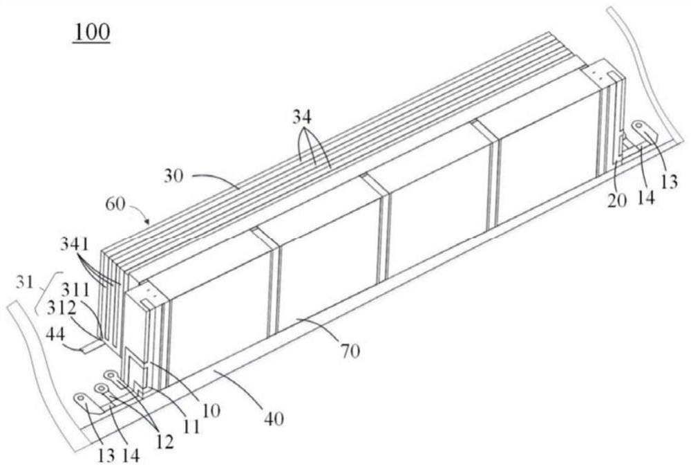
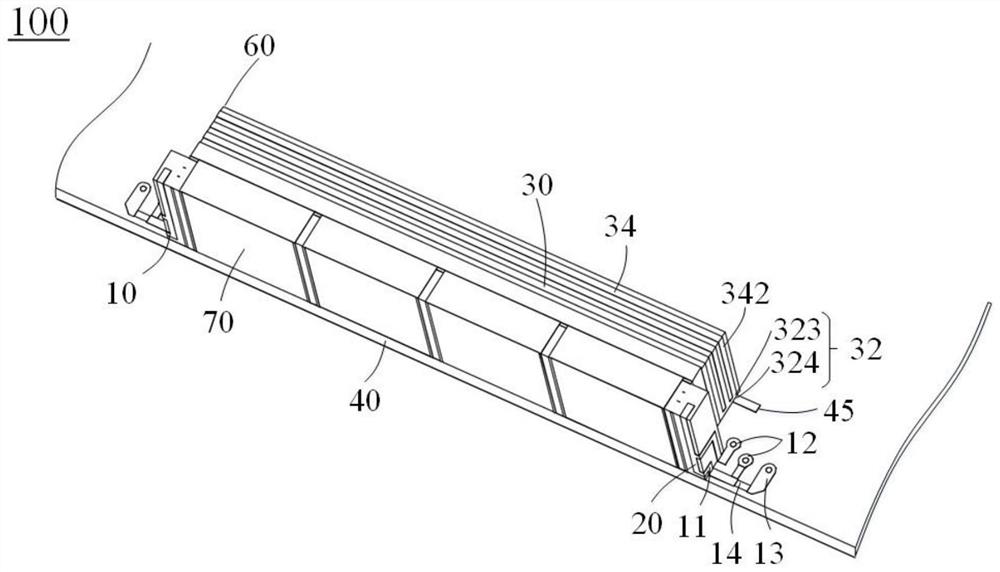
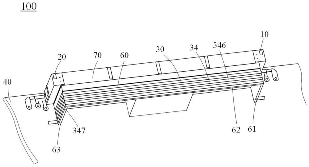
[0063] see figure 1 and figure 2 , figure 1 is a perspective view of the antenna structure disclosed in Embodiment 1 of the present application; figure 2 and image 3 respectively figure 1 Perspective views of different angles of the antenna structure shown. In one embodiment, an antenna structure 100 disclosed in the embodiment of the present invention includes a first antenna 10, a second antenna 20, and a three-dimensional decoupling structure 30 located on at least two planes. The three-dimensional decoupling structure 30 It includes a conductor, and at least part of the three-dimensional decoupling structure 30 is located in the space between the first antenna 10 and the second antenna 20 .

[0064] It can be understood that the space between the first antenna 10 and the second antenna 20 may be a three-dimensional space, which not only includes the space between the first antenna 10 and the second antenna 20 (as described The space through which any connecting li...

Embodiment 2

[0083] see Figure 5 , Figure 5 It is a perspective view of the antenna structure disclosed in Embodiment 2 of the present application. The solution of the antenna structure 100 in this embodiment is the same as the solution in the first embodiment and will not be repeated, and the differences of the antenna structure 100 in this embodiment will be focused on.

[0084] In the second embodiment, the three-dimensional decoupling structure 30 includes at least one wire 34, and the wire 34 includes a first wire part 343 and a second wire part 344, and the first wire part 343 and the second wire part 344 are electrically connected through the third electrical connection portion 33 . The third electrical connection part 33 includes one, two or more of another wire, an active electronic device, and a passive electronic device. Specifically, the active electronic device includes a switching element, such as a transistor or a micro-electro-mechanical system (MEMS), or an adjustable...

Embodiment 3

[0087] see Image 6 , Image 6 It is a perspective view of the antenna structure disclosed in Embodiment 3 of the present application. The solution of the antenna structure 100 in this embodiment is the same as the solution in the first embodiment and will not be repeated, and the differences of the antenna structure 100 in this embodiment will be focused on.

[0088] In the third embodiment, the three-dimensional decoupling structure 30 includes three wires 34, and each wire 34 includes a first wire part 343 and a second wire part 344, and the first wire part 343 and the corresponding wire The second wire portions 344 are electrically connected through the third electrical connection portion 33 .

[0089] Further, the third electrical connection part 33 includes one, two or more of another wire, an active electronic device, and a passive electronic device. Specifically, the active electronic device includes a switching element, such as a transistor or a micro-electro-mecha...


PUM


Abstract

The invention discloses an antenna structure and electronic equipment with the antenna structure. The antenna structure includes a first antenna, a second antenna, and a three-dimensional decoupling structure located on at least two planes, the three-dimensional decoupling structure includes a conductor, and at least part of the three-dimensional decoupling structure is located on the first antenna and the space between the second antenna. Compared with the prior art, the antenna structure disclosed in the present invention and the electronic equipment with the antenna structure can effectively achieve the antenna decoupling effect through the three-dimensional decoupling structure, so that the degree of degradation of the antenna performance due to coupling can be reduced, and at the same time The three-dimensional space of the system can be better utilized, and the horizontal area occupied by the system can be reduced to improve the utilization rate of the limited space, and there is no need to carry out metal clearance or avoidance on the circuit board, so as to maintain the integrity of the circuit board; Therefore, comprehensively speaking, the overall competitiveness of the product can be significantly improved.

Description

technical field [0001] The present invention relates to the technical field of antennas, in particular to an antenna structure and an electronic device having the antenna structure. Background technique [0002] In the 5G (fifth-generation mobile communication) era, due to the need to meet the communication requirements of MIMO (multi-input and multi-output, that is, multiple input and multiple output) with more channels, and to cover more new frequency bands, the number of antennas in the mobile phone Compared with the previous generation of mobile communication, the number of mobile communication generations has increased significantly, but the size of the mobile phone has not increased proportionally, so the distance between the antennas has been significantly shortened, and the coupling phenomenon between antennas of the same frequency or non-same frequency has become more serious (especially the same frequency or near-frequency antennas), the performance of the antenna ...

Claims


Application Information

Patent Timeline
Patent Type & Authority Patents(China)
IPC IPC(8): H01Q1/52H01Q21/00
CPCH01Q1/521H01Q21/00H01Q1/243H01Q1/38H01Q21/28H01Q9/04
Inventor 黄奂衢漆知行高大宋林虹周彦超
Owner ETHETA COMM TECH SHENZHEN CO LTD
Why Eureka
Try Eureka