Machining equipment for square tubes

A processing equipment, square technology, applied in the direction of metal processing equipment, metal processing, metal processing machinery parts, etc., can solve the problems of low processing efficiency, increased production cost, low chamfering efficiency, etc., to improve processing efficiency and realize automation , Good chamfering effect

Inactive Publication Date: 2017-05-10
天津福常科技有限公司
View PDF0 Cites 9 Cited by
  • Summary
  • Abstract
  • Description
  • Claims
  • Application Information

AI Technical Summary

Problems solved by technology

[0002] When further processing and assembling pipe workpieces, there are higher requirements on the cutting surfaces at both ends of the pipe to prevent the burrs formed during pipe cutting from affecting the processing accuracy or use requirements, so the inner and outer walls of both ends of the pipe are often They are all chamfered, so that the subsequent processing and assembly can be carried out smoothly, and also to prevent the staff from being scratched. However, the existing chamfering devices are often only aimed at round tube workpieces, and often a single tube is processed separately during processing. The corner efficiency is low. At present, square pipe fittings are often used in many fields such as construction, machinery manufacturing, and guardrails, but there is no special equipment that can be processed in batches, resulting in low processing efficiency and increased production costs. For this situation, The invention proposes a square tube processing equipment, through which the internal and external chamfering of square tubes can be realized in batches, and can be adapted to square tubes of various specifications and diameters, and can be automatically unloaded to realize the automation of the operation process, and the chamfering effect is better , improve processing efficiency and reduce production cost

Method used

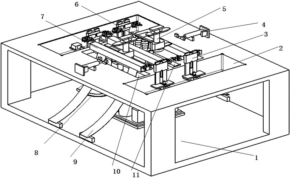
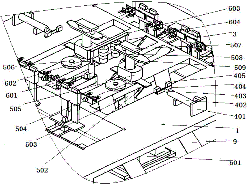
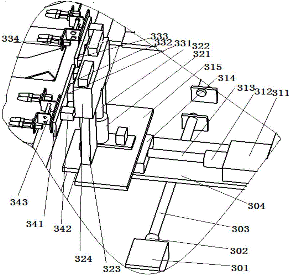

Image

  • Machining equipment for square tubes
  • Machining equipment for square tubes
  • Machining equipment for square tubes

Examples


Embodiment Construction

[0033] It should be noted that, in the case of no conflict, the embodiments of the present invention and the features in the embodiments can be combined with each other.

[0034] In describing the present invention, it should be understood that the terms "center", "longitudinal", "transverse", "upper", "lower", "front", "rear", "left", "right", " The orientations or positional relationships indicated by "vertical", "horizontal", "top", "bottom", "inner" and "outer" are based on the orientations or positional relationships shown in the drawings, and are only for the convenience of describing the present invention and Simplified descriptions, rather than indicating or implying that the device or element referred to must have a particular orientation, be constructed and operate in a particular orientation, and thus should not be construed as limiting the invention. In addition, the terms "first", "second", etc. are used for descriptive purposes only, and should not be understood ...


PUM


Abstract

The invention provides machining equipment for square tubes. The machining equipment comprises a bracket and two clamping mechanisms arranged on the bracket. First positioning mechanisms are arranged on the two sides of the two clamping mechanisms. Chamfering mechanisms are arranged in grooves. First blanking holes and second blanking holes are formed in the bracket. A first blanking rail and a second blanking rail are arranged on the bracket. A second positioning mechanism is arranged between the two second blanking holes. The second positioning mechanism comprises first hydraulic cylinders which are arranged in a mirror manner. A through hole is formed in the position, between the two first hydraulic cylinders, of the bracket. A first support is fixedly arranged between first ejector rods of the two first hydraulic cylinders. At least two layered positioning blocks are fixedly arranged at the bottom of the first support. By means of the machining equipment for the square tubes, the square tubes can be machined in batches, inner chamfering and outer chamfering of the square tubes of various specifications can be conducted at the same time, automatic blanking and automatic discharging after machining is completed can be achieved, the degree of automation is high, the machining efficiency is improved, and the production cost is lowered.

Description

technical field [0001] The invention belongs to the field of processing auxiliary equipment, in particular to a square tube processing equipment. Background technique [0002] When further processing and assembling pipe workpieces, there are higher requirements on the cutting surfaces at both ends of the pipe to prevent the burrs formed during pipe cutting from affecting the processing accuracy or use requirements, so the inner and outer walls of both ends of the pipe are often They are all chamfered, so that the subsequent processing and assembly can be carried out smoothly, and also to prevent the staff from being scratched. However, the existing chamfering devices are often only aimed at round tube workpieces, and often a single tube is processed separately during processing. The corner efficiency is low. At present, square pipe fittings are often used in many fields such as construction, machinery manufacturing, and guardrails, but there is no special equipment that can ...

Claims


Application Information

Patent Timeline
Patent Type & Authority Applications(China)
IPC IPC(8): B23D79/00B23Q3/08B23Q7/08
CPCB23D79/00B23Q3/082B23Q7/08
Inventor 崔海洋
Owner 天津福常科技有限公司
Why Eureka
Try Eureka