
Automatic pneumatic hammer device for pipe pile mould closing

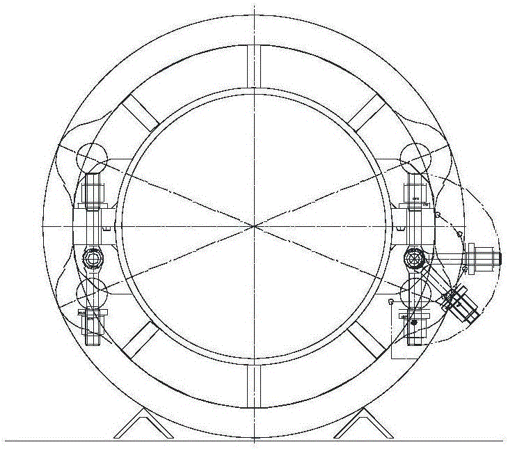
A mold and pipe pile technology is applied in the field of detection devices for pipe pile molds, which can solve the problems of time-consuming and laborious bolts, inability to apply pipe pile molds, and inability to achieve automation.

Active Publication Date: 2017-05-10
CHANGZHOU CHANGLI BOILER MFG INSTALLATION
View PDF11 Cites 16 Cited by
  • Summary
  • Abstract
  • Description
  • Claims
  • Application Information

AI Technical Summary

Problems solved by technology

[0005] Although the above-mentioned jackhammer mechanism solves the time-consuming and labor-intensive problem of manually tightening the bolts, the jackhammer mechanism still needs to manually turn the bolts over and embed them in the notches of the upper flange and the lower flange before tightening the bolts. Moreover, since the position of the blast stove is fixed, the position between two adjacent blast guns is also fixed, so this blast gun mechanism is only suitable for the fastening of pipe pile molds that are equidistant from the bolt spacing to the blast guns. , for example, if the distance between two wind guns is 100mm, then the distance between two adjacent bolts and notches on the upper mold or lower mold must also be 100mm, so that each wind gun can correspond to the bolts that need to be tightened. bolt
However, with the change of the pipe pile mold, the spacing between two adjacent bolts and notches on the upper and lower molds also changes, that is, the spacing between the bolts and the notches is not equidistant, for example, The distance between the current bolt and the next bolt is 100mm, and the distance between the next bolt and the next bolt is 80mm, so the above-mentioned wind cannon mechanism cannot be applied to such a pipe pile mold
Therefore, the above-mentioned wind gun mechanism can not meet the high requirement of automation

Method used


Image

  • Automatic pneumatic hammer device for pipe pile mould closing
  • Automatic pneumatic hammer device for pipe pile mould closing
  • Automatic pneumatic hammer device for pipe pile mould closing

Examples


Embodiment Construction

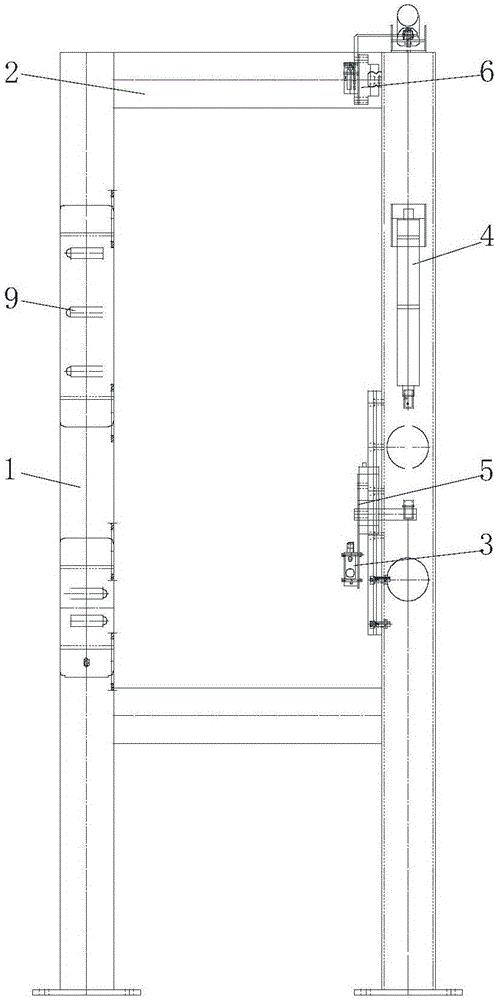
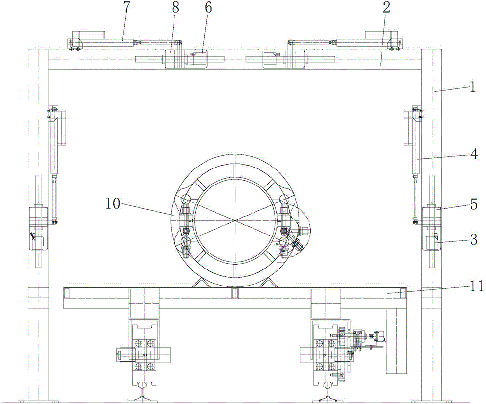
[0031] Such as Figure 3 to Figure 7 As shown, the automatic wind gun device for pipe pile mold clamping includes a detection device, a first frame for the pipe pile mold to pass through, a first linear drive mechanism, a second frame, a platform, a third frame, a first The lifting drive mechanism, the wind gun mechanism, the second linear drive mechanism, and the rotating mechanism that rotates the bolts hinged on the pipe pile mold, each part and the relationship between them are described in detail below:

[0032] The detection device is located upstream of the first frame. The detection device detects each notch on the pipe pile mold and the specific position of each bolt. The detection device includes:

[0033] Such as image 3 and Figure 4 As shown, the frame passing through the pipe pile mold 10; the frame is made up of at least two longitudinal beams 1 and at least one crossbeam 2, and the end of the longitudinal beam 1 is connected with the end of the crossbeam 2. ...


PUM


Abstract

The invention relates to an automatic pneumatic hammer device for pipe pile mould closing. A first sliding rail with the same movement direction as a pipe pile mould is arranged on a first frame; a first linear driving mechanism is arranged on the first frame; a second frame is in sliding fit on the first sliding rail; the power output end of the first linear driving mechanism is connected with the second frame; a platform is arranged on the second frame; a third frame is arranged on the platform; a first lifting driving mechanism is arranged along the longitudinal direction of the first frame and fixed on the third frame; the power output end of the first lifting driving mechanism penetrates through the third frame and is connected with a pneumatic hammer mechanism; when the speed of the first linear driving mechanism driving the second frame to move is the same as the movement speed of the pipe pile mould, the first lifting mechanism drives the pneumatic hammer mechanism to descend, and a bolt on the pipe pile mould is tightened by the pneumatic hammer mechanism in the synchronous movement process of the second frame and the pipe pile mould. The automatic pneumatic hammer device disclosed by the invention has the characteristic of high degree of automation on bolt tightening.

Description

technical field [0001] The invention relates to the technical field of pipe pile molds, in particular to a detection device for pipe pile molds. Background technique [0002] Such as figure 1 As shown, the pipe pile mold includes an upper mold and a lower mold, an upper flange is provided on the peripheral surface of the upper mold, a lower flange is provided on the peripheral surface of the lower mold, and both upper and lower flanges are provided with There are multiple notches, and the lower mold is provided with connecting plates located on opposite sides of the notches. The connecting plates are hinged through shafts and bolts (composed of nuts and screws). After the upper mold and the lower mold are closed, the lower mold The bolts are turned over so that the screw rods of the bolts are embedded in the recesses of the lower upper flange and the lower flange, and then the nuts on each bolt are tightened by the wind gun, so that the upper mold and the lower mold are fas...

Claims


Application Information

Patent Timeline
IPC IPC(8): B23P19/06
CPCB23P19/06
Inventor 周奇意
Owner CHANGZHOU CHANGLI BOILER MFG INSTALLATION
Learn More