
Micro injection molding machine with injection at right angles to the plasticizing axis

A right-angle, injection molding machine technology, applied in the field of plastic processing equipment, can solve problems such as bulky and complex structures, and achieve the effects of simplified support structure, simple transmission structure, and reduced axial size

Active Publication Date: 2019-02-22
ZHEJIANG UNIV
View PDF5 Cites 0 Cited by
  • Summary
  • Abstract
  • Description
  • Claims
  • Application Information

AI Technical Summary

Problems solved by technology

In order to achieve these two actions separately, it is necessary to design complex and bulky drive, transmission, and support structures in traditional injection molding machines.

Method used


Image

  • Micro injection molding machine with injection at right angles to the plasticizing axis
  • Micro injection molding machine with injection at right angles to the plasticizing axis
  • Micro injection molding machine with injection at right angles to the plasticizing axis

Examples


Embodiment Construction

[0030] The present invention will be further described below in conjunction with the accompanying drawings, and the purpose and effect of the present invention will become more obvious.

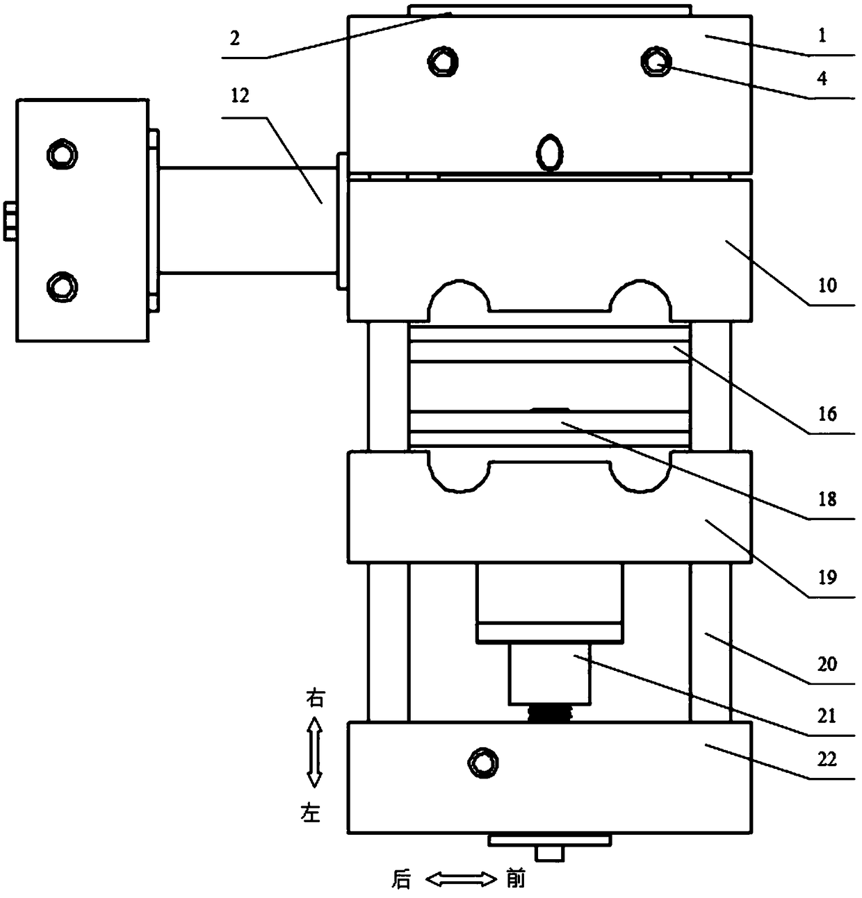
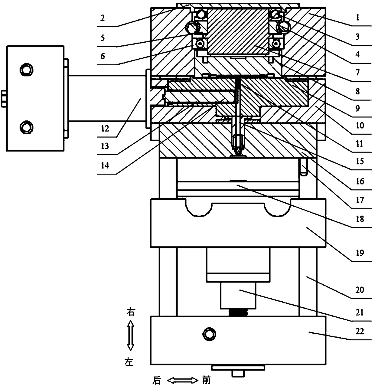
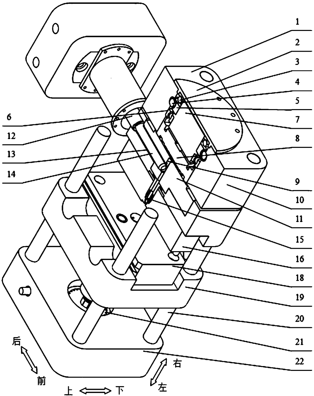
[0031] Such as figure 1 , figure 2 , image 3 As shown, a micro-injection molding machine whose injection is at right angles to the plasticizing axis includes a grinding disc plasticizing device, a mould, a mold clamping drive device and a clamping plate that are sequentially worn on the pull rod; it also includes an injection drive device; the injection The driving device is installed on the grinding disc plasticizing device, and the axis of the injection driving device and the axial direction of the grinding disc plasticizing device are perpendicular to each other.

[0032] The injection drive device 1 includes a drive mechanism and a spline ball screw 101, the drive mechanism drives the spline ball screw 101 to realize the reciprocating motion of the spline ball screw 101 along its own ...


PUM


Abstract

The invention discloses a micro-injection machine with a right angle formed between an injection molding axis and a plastifying axis. The micro-injection machine comprises a millstone plastifying device, a die, a die assembly driving device and a clamping plate and further comprises an injection driving device. The millstone plastifying device, the die, the die assembly driving device and the clamping plate sequentially penetrate a pull rod. The injection driving device is installed on the millstone plastifying device, and the axis where the injection driving device is located is vertical to the axis where the millstone plastifying device is located. According to the micro-injection machine with the right angle formed between the injection molding axis and the plastifying axis, an injection molding part is arranged behind a plastifying part, the axial size of the plastifying part is reduced, the structure is simple and compact, the occupied space is small, and molding actions are smoother; and movements of the injection molding part and the plastifying part of the micro-injection machine with the right angle formed between the injection molding axis and the plastifying axis are separated, mutual interference is reduced, and therefore the stability and performance of the machine are improved.

Description

technical field [0001] The invention belongs to the technical field of plastic processing equipment and relates to a miniature injection molding machine whose injection is at right angles to the plasticizing axis. Background technique [0002] Injection molding machines usually consist of plasticizing, injection, mold clamping and other parts. The plasticizing part of the traditional injection molding machine uses the long rod-shaped screw in the rotating barrel to realize the plasticizing action of the plastic, and another set of power system drives the screw to move along the axis to realize the injection action. In order to realize these two actions separately, it is necessary to design complex and bulky driving, transmission and supporting structures in the traditional injection molding machine. [0003] Due to the use of a disc-type plasticizing device different from the traditional plasticizing part, the structure of the plasticizing part can be simplified and compact...

Claims


Application Information

Patent Timeline
Patent Type & Authority Patents(China)
IPC IPC(8): B29C45/46B29C45/53B29C45/58
CPCB29C45/464B29C45/531B29C45/586
Inventor 李凌丰毛晨翁旭吕富珍
Owner ZHEJIANG UNIV
Learn More