Dynamic adjustment method for process parameters in selective laser sintering sub regions

A technology of laser selective sintering and process parameters, which is applied in processing data acquisition/processing, processing and manufacturing, additive processing, etc., can solve the problems of reducing or not considering the pertinence of parts control, reducing the amount of temperature field information, etc., to achieve quality Good, direct and effective temperature control, flexible and effective temperature field control effect

Inactive Publication Date: 2017-05-10
XI AN JIAOTONG UNIV
View PDF5 Cites 30 Cited by
  • Summary
  • Abstract
  • Description
  • Claims
  • Application Information

AI Technical Summary

Problems solved by technology

Using the average temperature as the control basis greatly reduces the amount of information contained in the original temperature field, and cannot accurately reflect the temperature distribution of the powder bed, making it difficult to obtain an ideal temperature field control effect
[0005] In addition, most of the existing SLS temperature field control technologies are for the control of the preheating system, which does not involve the section information of the parts and the dynamic process parameter control
Regardless of the section information of the part, the pertinence of the control is reduced, and because the temperature field is constantly changing with time, if the process parameters are not dynamically adjusted, the changes in the temperature field are adjusted in time, and a single process parameter is used to control the temperature field. The sintering of the powder bed will definitely affect the control effect of the temperature field

Method used


Image

  • Dynamic adjustment method for process parameters in selective laser sintering sub regions
  • Dynamic adjustment method for process parameters in selective laser sintering sub regions
  • Dynamic adjustment method for process parameters in selective laser sintering sub regions

Examples


Embodiment Construction

[0031] The content of the present invention will be further described below in conjunction with the accompanying drawings and embodiments, but the practical application of the invention is not limited to the following embodiments.

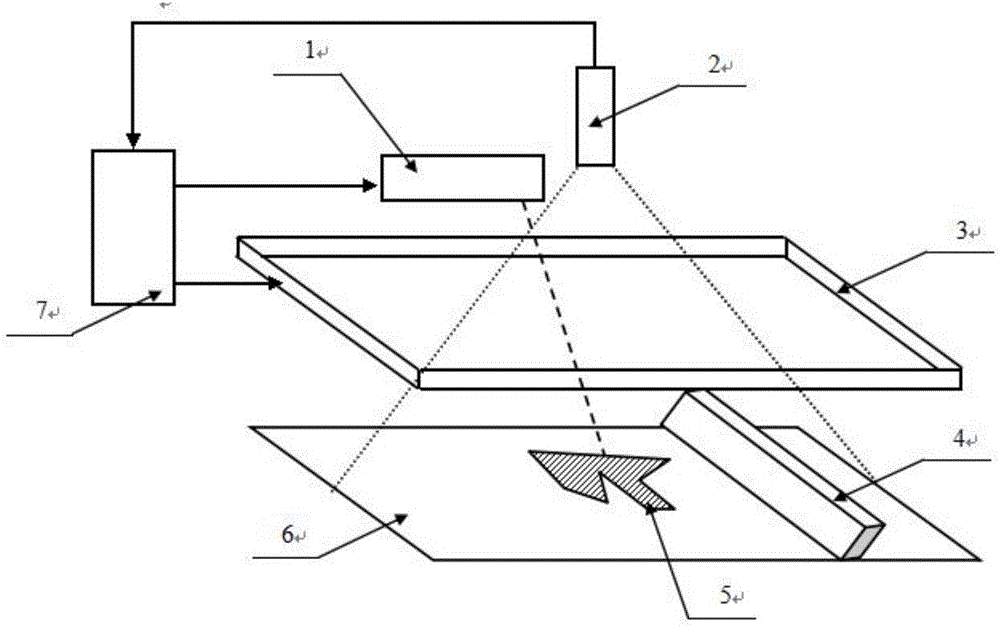
[0032] The composition of the working system of this embodiment is as follows: figure 1 As shown, in the processing process of one layer, a layer of powder is laid on the powder bed plane 6 by the powder spreading device 4 first, and after the powder spreading is completed, the infrared thermal imager 2 detects the temperature distribution of the powder bed plane 6, and then the temperature field The distribution information is sent to the computer 7, and the computer 7 analyzes and processes the incoming temperature field data, and then controls the preheating device 3 or the laser 1 to perform corresponding operations to complete the sintering of a slice profile 5, and so on, and finally completes Sintering of entire three-dimensional objects.

...


PUM


Abstract

Provided is a dynamic adjustment method for process parameters in selective laser sintering sub regions. Powder bed machining plane temperature field information is detected through a thermal imager in the SLS machining process, a powder bed is divided into different regions through the detected temperature field information according to the temperature, each region to be machined is further divided into regions belonging to different temperature intervals in combination with slice contour information, the machining process parameters, such as the laser power, the scanning speed and the scanning path, used when the regions are machined are adjusted in a targeted manner, multiple times of detection can be conducted in the machining process, and the process parameters are adjusted in time according to the temperature field change. By the adoption of the dynamic adjustment method, the powder bed temperature field information can be more comprehensively used, and in combination with corresponding control operations, the more direct and precise temperature control is achieved, so that the uniformity of the temperature field of the powder bed is improved, and accordingly the quality of SLS parts is improved.

Description

technical field [0001] The invention relates to the technical field of selective laser sintering, in particular to a method for dynamically adjusting process parameters of laser selective sintering and sub-area. Background technique [0002] Selective Laser Sintering (SLS) is a rapid prototyping technology that uses laser heating powder sintering. In SLS technology, the laser beam selectively sinters the powder bed according to the layered cross-section information under the control of the computer. The local input heat source causes the distribution of the temperature field of the powder bed during the sintering process to be uneven and unstable, which makes the The control of the temperature field is extremely difficult. However, the temperature field distribution is an important factor determining the quality of SLS processing. If the temperature field gradient is too large, the material system will shrink inconsistently, which will easily cause deformation, warping and ...

Claims


Application Information

Patent Timeline
Patent Type & Authority Applications(China)
IPC IPC(8): B29C64/153B29C64/393B33Y50/02
CPCB33Y50/02
Inventor 田小永何顺文同治强曹毅李涤尘
Owner XI AN JIAOTONG UNIV
Why Eureka
Try Eureka