Electric bicycle with laterally-arranged driving device, and laterally-arranged driving device thereof
A drive device, electric vehicle technology, applied in wheel transmission, rider drive, vehicle parts, etc., can solve the problems of poor motor heat dissipation, small motor, insufficient power and so on
- Summary
- Abstract
- Description
- Claims
- Application Information
AI Technical Summary
Problems solved by technology
Method used
Image
Examples
Embodiment 1
[0035] Embodiment 1: A side drive device for an electric vehicle
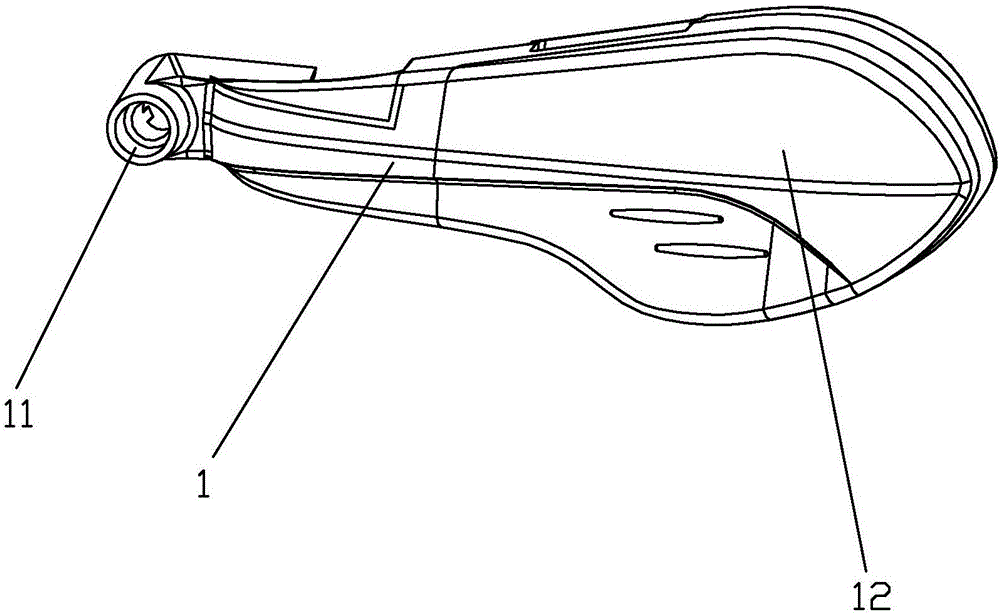
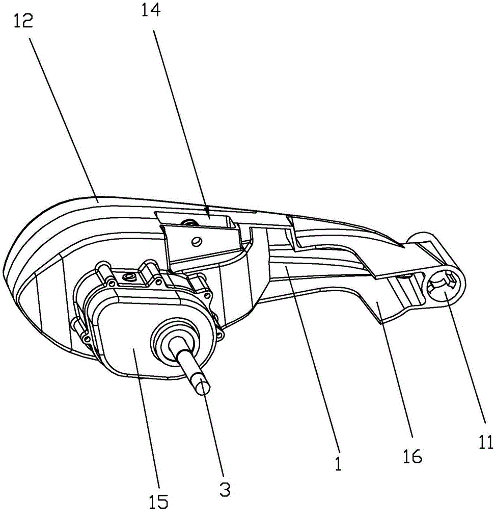
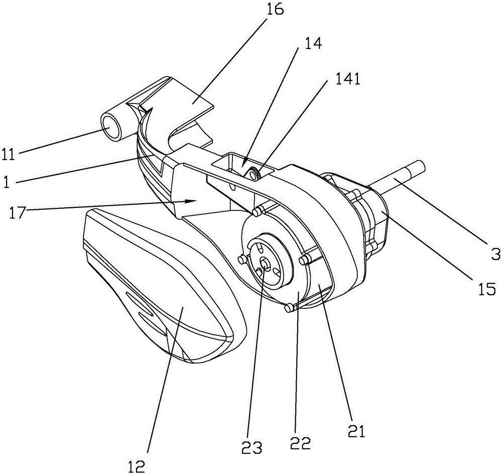
[0036] Such as figure 1 with figure 2 As shown, a side drive device for an electric vehicle includes a substantially L-shaped fork body 1, and the fork body 1 gradually increases from the front end to the rear end. The front end of the fork body 1 is horizontally provided with a connecting hole 11 for being rotationally connected with the vehicle frame and the rear fork 6 matched therewith. There are three reinforcing strips 111 (such as Figure 4 shown). The setting of the reinforcing bar 111 can enhance the structural strength of the connection hole 11 at this place.
[0037] The fork body 1 gradually protrudes from the middle to its inner and outer sides. Such as image 3 As shown, the middle and rear part of the fork body 1 is provided with a motor chamber 17, the motor chamber 17 is recessed inside the fork body 1, the opening of the motor chamber 17 faces the outside of the fork body 1, and the ope...
Embodiment 2
[0042] Embodiment 2: A side drive device for an electric vehicle
[0043] Such as Figure 5 with Image 6 As shown, the difference between the second embodiment and the first embodiment is that the inner surface of the front part of the fork body 1 of the second embodiment is provided with a plurality of intersecting reinforcing ribs 20, and the reinforcing ribs 20 are connected with the flanges 16 at the upper and lower ends of the front part of the fork body 1. The integrated body is used to strengthen the strength of the front end of the fork body 1, so that the structural strength of the fork body 1 is higher, and it is more suitable for the requirements of heavy load and bumpy road surface. The inner side of the front part of the fork body 1 is also provided with a protruding post 13, and the end of the protruding post 13 is provided with a threaded hole. 1 connected as one. At the same time, interlaced reinforcing ribs 20 are arranged in the motor chamber 17 to streng...
Embodiment 3
[0044] Embodiment 3: A side-mounted electric vehicle with a driving device
[0045] Such as Figure 7 As shown, a drive device side-mounted electric vehicle includes a vehicle frame 8, and one side of the rear end of the vehicle frame 8 is provided with the electric vehicle side drive device in Embodiment 1; the other side of the vehicle frame 8 rear end is installed with the The back fork 66 (such as Image 6 shown). The shape of the rear fork 66 is similar to the fork body 11, and the other end of the wheel shaft 3 is rotatably connected on the rear fork 6, and the rear wheel 7 of the electric vehicle is installed in the middle part of the wheel shaft 3. A shock absorber is connected in the shock absorber groove 14 of the fork body 11 , and the other end of the shock absorber is connected with the vehicle frame 8 . Between fork body 1 and the connecting hole 11 of rear fork 6 front ends, be provided with connecting shaft, half of connecting shaft is in the connecting hole...
PUM
 Abstract
Description
Claims
Application Information
 - R&D
- Intellectual Property
- Life Sciences
- Materials
- Tech Scout
- Unparalleled Data Quality
- Higher Quality Content
- 60% Fewer Hallucinations
Browse by: Latest US Patents, China's latest patents, Technical Efficacy Thesaurus, Application Domain, Technology Topic, Popular Technical Reports.
© 2025 PatSnap. All rights reserved.Legal|Privacy policy|Modern Slavery Act Transparency Statement|Sitemap|About US| Contact US: help@patsnap.com


