Automatic material distribution counting and stacking machine and control method thereof

A control method and fabric technology, applied in the direction of automatic packaging control, packaging, packaging protection, etc., can solve the problems of easy contamination of the blade surface, error-prone counting, low efficiency, etc., and achieve the effects of high safety, accurate counting and high efficiency.

Inactive Publication Date: 2017-05-10
安徽华天机械股份有限公司
View PDF7 Cites 0 Cited by
  • Summary
  • Abstract
  • Description
  • Claims
  • Application Information

AI Technical Summary

Problems solved by technology

[0006] In view of the problems that the existing metal blades adopt manual counting and stacking, which are easy to pollute the surface of the blades, the hands are easy to be scratched, the counting is easy to make mistakes and the efficiency is low, the present invention provides an automatic cloth measuring coder, which can stack the blades as required Palletizing, automatic machine operation, accurate counting, high efficiency, no manual intervention, no impact on the surface quality of the blade, high safety

Method used


Image

  • Automatic material distribution counting and stacking machine and control method thereof
  • Automatic material distribution counting and stacking machine and control method thereof
  • Automatic material distribution counting and stacking machine and control method thereof

Examples


Embodiment 1

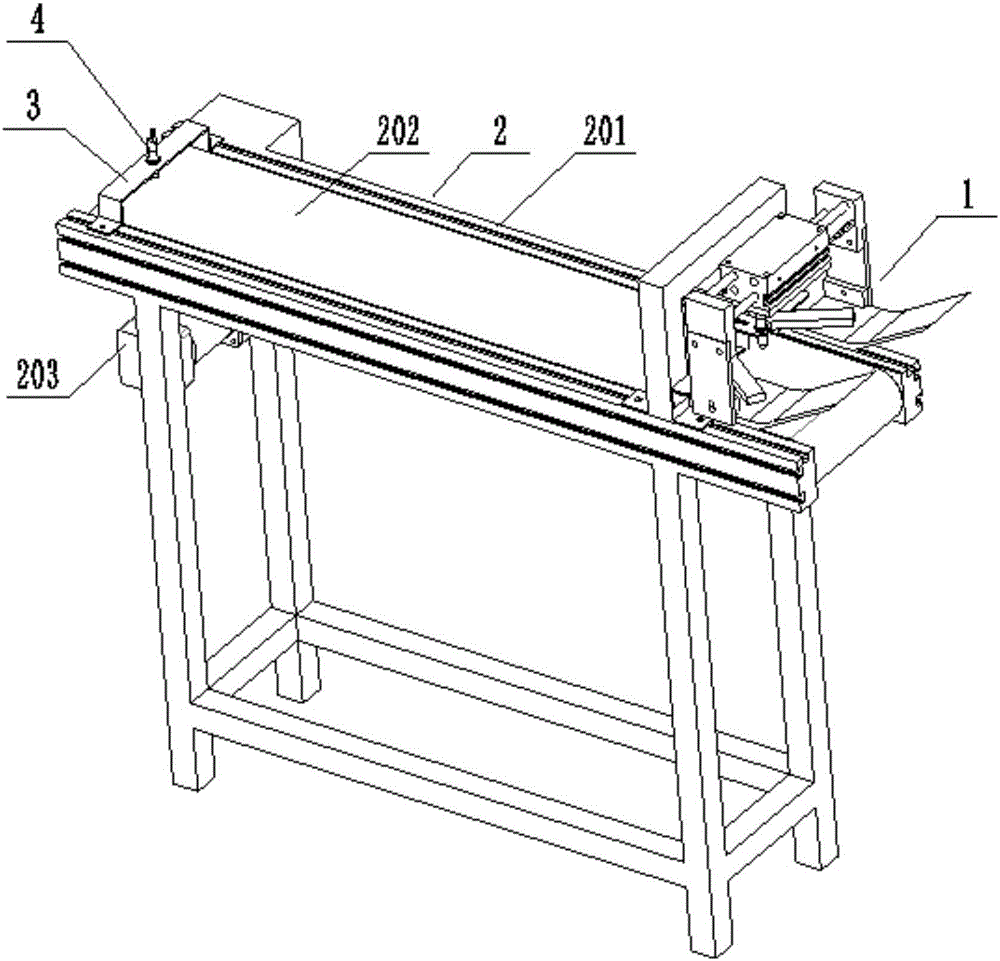
[0050] Such as figure 1 As shown, an automatic cloth measuring code machine of this embodiment includes a cloth mechanism 1 and a conveying mechanism 2; wherein, as a solution of this embodiment, the conveying mechanism 2 is a belt conveyor, which includes a frame and a set A pair of beams 201 on the frame, a belt 202 is installed by a drum between a pair of beams 201, a motor 203 is installed on the frame, and the motor 203 is connected with the drum through a reduction box, thereby driving the drum to rotate and driving the belt 202 to move. Of course, the use of a belt conveyor for the conveying mechanism 2 is only a preferred mode of this embodiment, and other structures in the prior art can also be used, as long as the conveying function can be realized. In this embodiment, the upper surface of the beam 201 is provided with a T-shaped groove, which facilitates the detachable installation of other components, and the position can be adjusted at will.

[0051] Described ma...

Embodiment 2

[0056] When the material does not need to enter the next process, the stacking of the material on the conveying mechanism 2 may exceed its stroke, and the problem of material drop occurs. Based on this premise, the automatic cloth measuring machine of this embodiment is based on the structural basis of embodiment On the conveying mechanism 2, a limit proximity switch 4 is set at the end away from the cloth mechanism 1, which is used to sense the limit position of the material conveyed by the conveying mechanism 2. The limit proximity switch 4 is fixed by the switch holder 3 installed on the beam 201. During use, the limit proximity switch 4 senses the material, and sends a signal to the control unit to stop the conveying mechanism 2 and continue to transport forward. At this time, the materials on the conveying mechanism 2 can be packed into boxes and other operations.

Embodiment 3

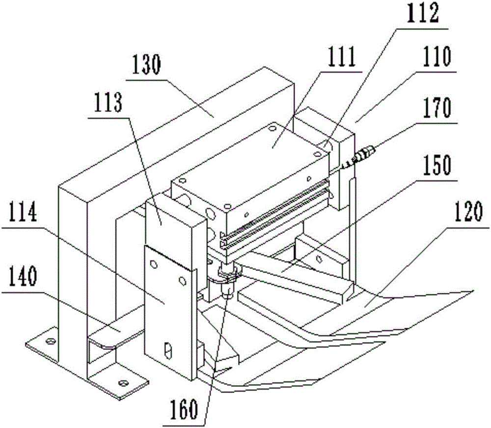
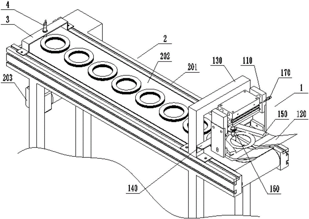
[0058] This embodiment provides a control method for an automated cloth measuring coder, which is used to control and use the cloth measuring coder in Embodiment 2 to perform palletizing operations of metal circular blades, combined with image 3 and Figure 4 As shown, the specific steps are as follows: firstly, the drive cylinder 110 of the material distribution mechanism 1 drives the material receiving plate 120 to draw in, that is, the piston rods 112 on both sides of the cylinder body 111 shrink, and the fingers 113 drive the two material receiving plates 120 to approach each other to achieve gathering. Then, the blade falls on the material receiving plate 120, and is stuck between two material stoppers 150, and is received and positioned. At the same time, the cloth proximity switch 160 senses the blade, generates an electrical signal and transmits the control element, and the control element controls The drive cylinder 110 moves, the piston rod 112 of the drive cylinder...


PUM


Abstract

The invention discloses an automatic material distribution counting and stacking machine and a control method thereof and belongs to the field of automatic mechanical equipment. The equipment comprises a material distribution mechanism and a conveying mechanism. The material distribution mechanism comprises a driving cylinder and a material receiving plate. The material receiving plate is used for receiving or putting down materials, and the driving cylinder drives the material receiving plate to be opened or closed. The conveying mechanism receives the materials falling from the material receiving plate and conveys the materials. The material distribution mechanism is provided with a material distribution proximity switch, when the material receiving plate receives the materials, the material distribution proximity switch generates induction signals and transmits the signals to a counter, and therefore automatic counting can be achieved. A magnetic switch is arranged on a cylinder body of the driving cylinder, a magnetic ring installed in a piston rod in the cylinder body can be inducted, and therefore electric signals are generated. Blades cam be stacked through the equipment, automatic operation is achieved, counting is accurate, high efficiency is achieved, no manual intervention is needed, the surfaces of the blades are not damaged, and high safety is achieved. The control method of the automatic material distribution counting and stacking machine can control the equipment to complete counting and stacking operation of the blades.

Description

technical field [0001] The invention belongs to the field of automatic mechanical equipment, and more specifically relates to an automatic cloth measuring coder and a control method thereof. Background technique [0002] Since the reform and opening up, China's economic development has achieved world-renowned achievements. Its economic strength and comprehensive national strength have been greatly developed in recent decades. The economic strength continues to rise and the economic growth rate continues to accelerate. China The economy has become the focus of attention of countries all over the world. However, in recent years, with the changes in the international environment and the sharp increase in labor costs, Chinese companies are facing a transformation and development process from quantitative changes to qualitative changes. Improvement of product quality, improvement of production efficiency, and reduction of labor costs are all enterprises that break the deadlock. ...

Claims


Application Information

Patent Timeline
Patent Type & Authority Applications(China)
IPC IPC(8): B65B35/50B65B35/44B65B57/20B65B57/14
CPCB65B35/50B65B35/44B65B57/14B65B57/20
Inventor 陶华陶鹏
Owner 安徽华天机械股份有限公司
Why Eureka
Try Eureka