Delaying bin

A silo and storage cavity technology, which can be used in the destacking of objects, stacking of objects, conveyor objects, etc., which can solve the problems of inflexible use and large space.

Active Publication Date: 2017-05-10
GEER TECH CO LTD
View PDF11 Cites 1 Cited by
  • Summary
  • Abstract
  • Description
  • Claims
  • Application Information

AI Technical Summary

Problems solved by technology

The current practice is to design the delay mechanism as an assembly line, but the assembly line delay mechanism takes up too much space and is not flexible to use

Method used


Image

  • Delaying bin
  • Delaying bin
  • Delaying bin

Examples


Embodiment Construction

[0028] Below in conjunction with accompanying drawing and embodiment, further elaborate the present invention.

[0029] The orientations involved in this manual are all based on the orientation of the time-delay silo of the present invention when it is working normally, and are not limited to its orientation during storage and transportation, and only represent relative positional relationships, not absolute positional relationships.

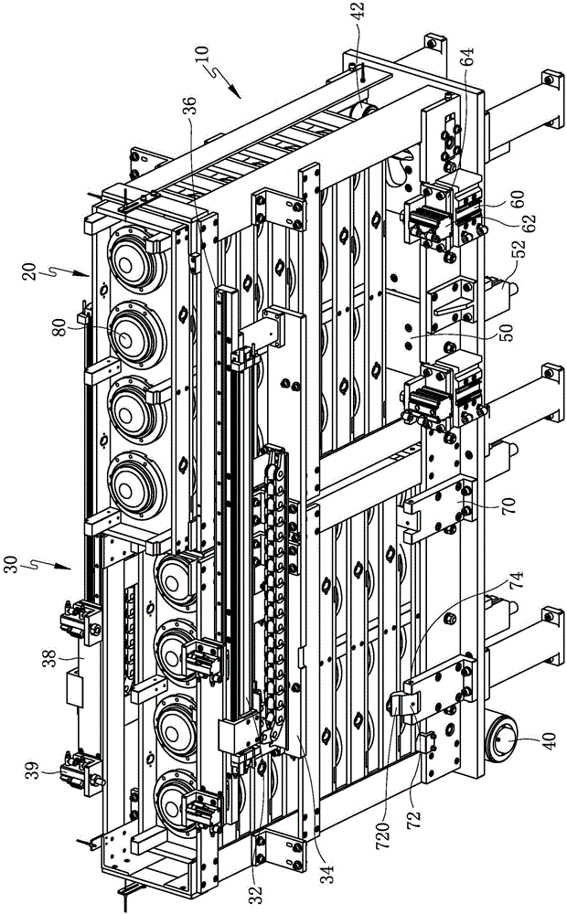
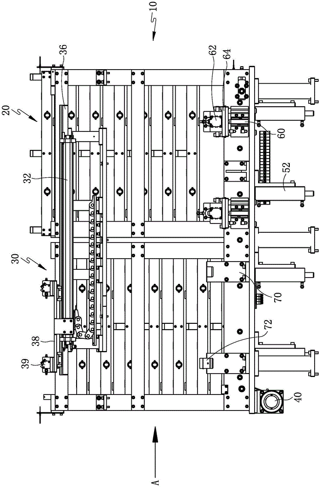
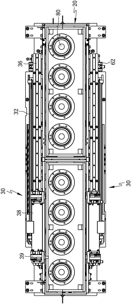
[0030] Such as figure 1 , figure 2 and Figure 5 Commonly shown, a kind of time-delay silo comprises a support frame 10, and the support frame 10 comprises a rectangular installation base plate 12 placed horizontally, a plurality of legs 14 are fixed on the lower side of the installation base plate 12, and the upper side of the installation base plate 12 is vertical A frame is fixed to the direction, and the frame and the installation base plate 12 together form a product storage cavity, the product storage cavity is open at the upper end, an...


PUM


Abstract

The invention discloses a delaying bin and relates to the technical field of production equipment of electroacoustic products. The delaying bin comprises two accommodating cavities communicated side by side, wherein the two accommodating cavities are provided with multiple trays in a vertical superposition mode, products are arranged on the trays, and the trays sequentially move in the product accommodating cavities in the clockwise direction or anticlockwise direction. Transverse moving mechanisms are installed on the inner sides of the product accommodating cavities. Upper top plates are installed at the bottoms of the two accommodating cavities. Bearing mechanisms are oppositely arranged on two sides of each tray moving from top to bottom of the accommodating cavities, and each bearing mechanism comprises a second vertical movement power device and a first longitudinal movement power device installed on a power output part of the second vertical movement power device. Supporting mechanisms are oppositely arranged on two sides of each tray moving from top to bottom of the accommodating cavities. The delaying bin can automatically complete a product delaying process and meanwhile is compact in structure, small in occupied space and high in automation degree.

Description

technical field [0001] The invention relates to the technical field of production equipment of electro-acoustic products, in particular to a sound box and a time-delay feed bin in the production process of a speaker for automobiles. Background technique [0002] The horn is an electro-acoustic component used to convert electrical signals into sound signals. At present, in the production process of speakers and car speakers, the bonding of the diaphragm and the speaker shell requires a delay process, that is, after the diaphragm and the shell are bonded, it needs to be placed naturally for more than 30 minutes before the next process can be carried out. In order to organically integrate various Procedure, just need a kind of time-delay mechanism, and do not have better time-delay mechanism to solve this technical problem at present. The current practice is to design the time-delay mechanism as an assembly line, but the pipeline-type time-delay mechanism takes up too much spa...

Claims


Application Information

Patent Timeline
Patent Type & Authority Applications(China)
IPC IPC(8): B65G57/32B65G59/12B65G59/06B65G47/90B65G47/04
CPCB65G47/04B65G47/90B65G57/32B65G59/067B65G59/12B65G2201/0258
Inventor 华开春
Owner GEER TECH CO LTD
Why Eureka
Try Eureka