Suction disc device with ejection structure

An ejector mechanism and suction cup technology, applied in the directions of transportation and packaging, thin material handling, object separation, etc., can solve problems such as damage, object deformation, affecting production efficiency, etc., to reduce production costs, save time, and improve production efficiency. Effect

Inactive Publication Date: 2017-05-10
天津日博工业技术有限公司
View PDF0 Cites 8 Cited by
  • Summary
  • Abstract
  • Description
  • Claims
  • Application Information

AI Technical Summary

Problems solved by technology

However, this kind of suction cup has the following disadvantages: when picking up items, because the end is a vacuum suction cup, the suction force is relatively large, and grabbing thinner or less hard items, such as films, will deform the item, causing creases or even damage ,Affect
When dropping items, due to static electricity and other reasons, the items cannot fall from the suction cup in time, which affects production efficiency
Especially in occasions where the quality of the items to be picked and placed is high, the general picking and placing mechanism can no longer meet the requirements

Method used


Image

  • Suction disc device with ejection structure
  • Suction disc device with ejection structure

Examples


Embodiment Construction

[0023] It should be noted that, in the case of no conflict, the embodiments of the present invention and the features in the embodiments can be combined with each other.

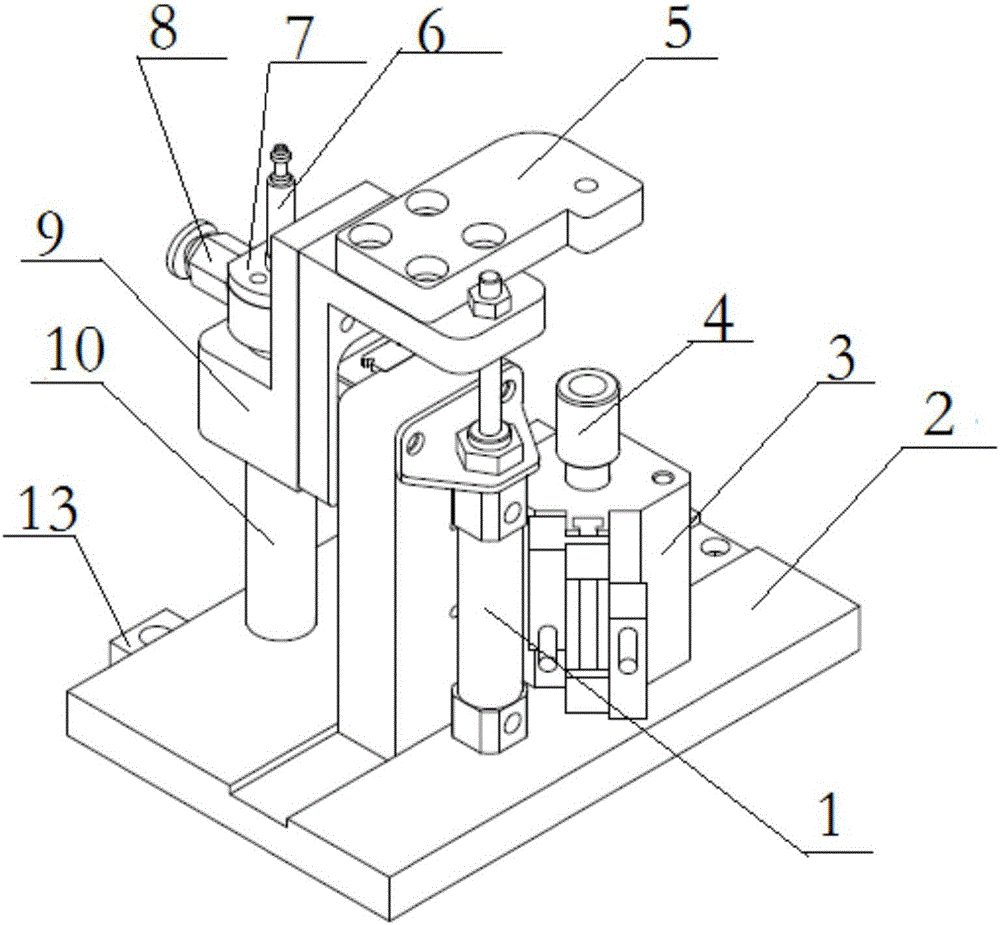
[0024] In describing the present invention, it should be understood that the terms "center", "longitudinal", "transverse", "upper", "lower", "front", "rear", "left", "right", " The orientations or positional relationships indicated by "vertical", "horizontal", "top", "bottom", "inner" and "outer" are based on the orientations or positional relationships shown in the drawings, and are only for the convenience of describing the present invention and Simplified descriptions, rather than indicating or implying that the device or element referred to must have a particular orientation, be constructed and operate in a particular orientation, and thus should not be construed as limiting the invention. In addition, the terms "first", "second", etc. are used for descriptive purposes only, and should not be understood ...


PUM


Abstract

The invention provides a suction disc device with an ejection structure. The suction disc device comprises a base, a suction disc mechanism, an ejection mechanism, a hoisting mechanism and a limiting mechanism, wherein the ejection mechanism is fixedly connected to the suction disc mechanism; the hoisting mechanism drives the suction disc mechanism to do vertical movement; the limiting mechanism has a limiting effect on a route of the hoisting mechanism; the suction disc mechanism comprises a suction disc and a quick plug connector; a first through hole is formed in the end of the suction disc; the first through hole is communicated with the quick plug connector; a second through hole is further formed in the suction disc; the ejection mechanism comprises a push rod, an air cylinder seat and an ejection air cylinder; the ejection air cylinder and the suction disc are fixed on the air cylinder seat; the push rod is fixedly connected to a piston rod of the ejection air cylinder; and the push rod is located in the second through hole. When the suction disc device with the ejection structure, provided by the invention, is used for sucking, thin-sheet type objects are not bent and deformed; and influences of static electricity, friction and the like can also be overcome when the objects are put down and the objects can easily fall into an effective appointed region.

Description

technical field [0001] The invention belongs to the field of picking and placing objects, in particular to a suction cup device with an ejection structure. Background technique [0002] In automatic production, the grabbing and transporting of objects is an important link. In the existing technology, the structure of picking and placing small and thin sheet objects generally adopts a structure with a suction cup at the end, and the suction cup is made of rubber or silica gel. However, this kind of suction cup has the following disadvantages: when picking up items, because the end is a vacuum suction cup, the suction force is relatively large, and grabbing thinner or less hard items, such as films, will deform the item, causing creases or even damage ,Affect. When dropping items, due to reasons such as static electricity, the items cannot fall from the suction cup in time, which affects production efficiency. Especially in the occasions where the quality requirements for th...

Claims


Application Information

Patent Timeline
Patent Type & Authority Applications(China)
IPC IPC(8): B65H3/08B65H5/14
CPCB65H3/0816B65H3/0883B65H5/14B65H2401/13B65H2401/11
Inventor 毛锦明
Owner 天津日博工业技术有限公司
Why Eureka
Try Eureka