A tensioning mechanism for film-attached winding tube core

A technology of tensioning mechanism and film sticking, which is applied in the directions of winding strips, thin material handling, transportation and packaging, etc., and can solve problems such as unfavorable processing efficiency and increased costs

Active Publication Date: 2019-03-08
苏州威仕薄膜科技有限公司
View PDF1 Cites 0 Cited by
  • Summary
  • Abstract
  • Description
  • Claims
  • Application Information

AI Technical Summary

Problems solved by technology

The above mechanism also needs to install suction equipment, which not only increases the cost but also is not conducive to improving the processing efficiency

Method used


Image

  • A tensioning mechanism for film-attached winding tube core
  • A tensioning mechanism for film-attached winding tube core
  • A tensioning mechanism for film-attached winding tube core

Examples


Embodiment Construction

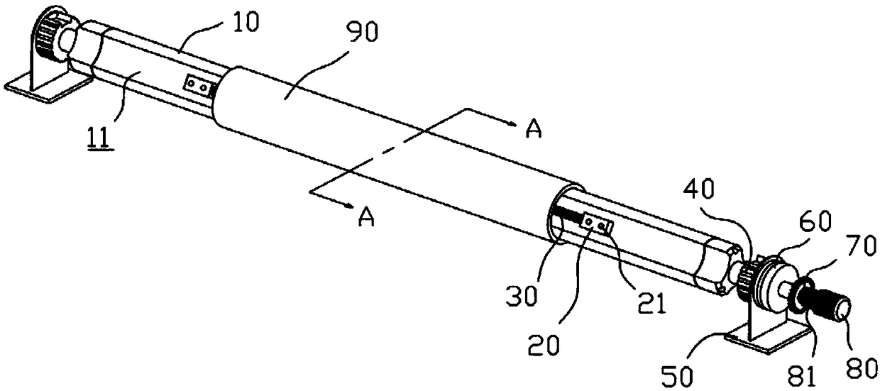
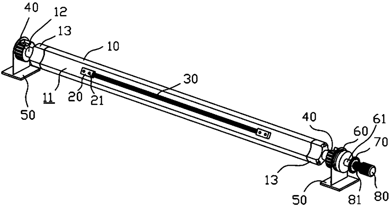
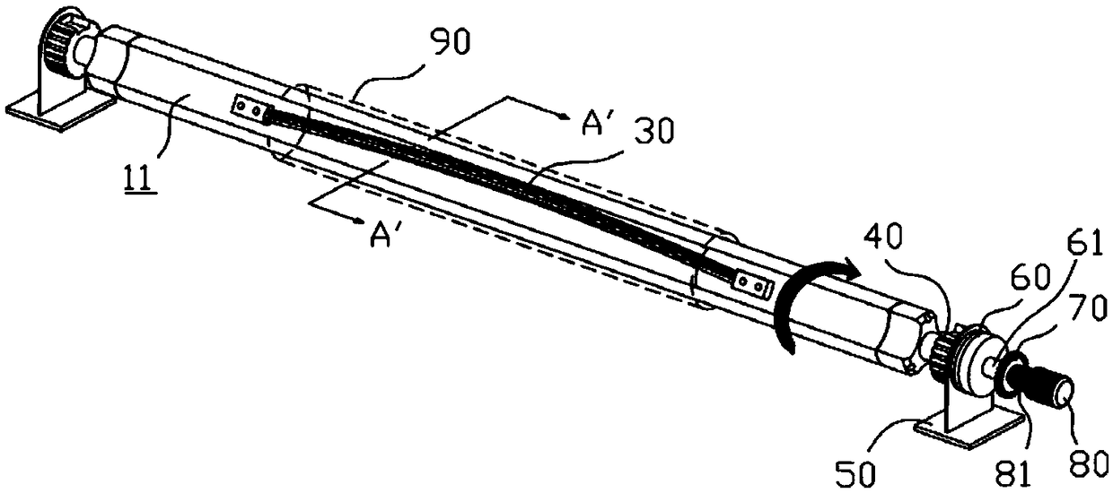
[0018] Such as Figure 2 to Figure 4 As shown, a tensioning mechanism for film-attached winding tube cores includes a main shaft 10, two locking blocks 13 are respectively provided at both ends of the main shaft 10, and the two locking blocks 13 are fixed to the main shaft 10 by several bolts. , the middle part of the main shaft 10 is the central shaft 12, the central shaft 12 is installed through the locking block 13, the central shaft 12 is fixed in the base 50 through the mounting block 40, and the base 50 is installed in the film processing machine tool On the frame; there are three big gaps 11 among the said main shaft 10, the big gaps 11 are arc-shaped, the three big gaps 11 are circumferentially arranged, and each big gap 11 is provided with two The fixing blocks 20 are provided with a tensioning strip 30 between the two fixing blocks 20 .

[0019] Such as Figure 4 As shown, the tension strip 30 is provided with a small gap 31 , and the outer diameter of the tension ...


PUM


Abstract

The invention discloses a tensioning mechanism of a film-pasted coiled tube core. The tensioning mechanism comprises a spindle, wherein two locking blocks are arranged at two ends of the spindle respectively and are fixed to the spindle through a plurality of bolts, the middle of the spindle is a central shaft, the central shaft penetrates through the locking blocks for installation, the central shaft penetrates an installing block to be fixed in a base, and the base is installed on a rack of a film-pasted machining machine tool. The spindle is provided with three large gaps, the gaps are circular-arc-shaped and are arranged peripherally, two fixing blocks are arranged in each large gap, and a tensioning strip is arranged between the two fixing blocks. The tensioning mechanism of an existing film-pasted coiled tube core is improved in design, the plastic tensioning strip is designed and installed in the large gaps, so that the tube core firmly attaches to the tensioning strip during rotation, and a tensioning effect is played on the tube core.

Description

Technical field: [0001] The invention relates to the technical field of film pasting and winding machinery, in particular to a tensioning mechanism for film pasting and winding tube cores. Background technique: [0002] In order to facilitate the storage and handling of the film, the film is generally wrapped around the city. In this case, a winding machine is used to roll the loose film onto the die through the winding machine. Therefore, the die needs to be fixed on the fixing device first. In the above, the application number is 201310163736.6, which includes a suction device and a winding shaft. The winding shaft is provided with a central hole with one end open and one end closed. The shaft is also formed with a number of air holes that are perpendicular to the axial direction and communicate with the central hole. The openings of the air holes are arranged on the circumferential surface of the winding shaft. There are several elongated waist-shaped holes depressed dow...

Claims


Application Information

Patent Timeline
Patent Type & Authority Patents(China)
IPC IPC(8): B65H18/04B65H18/10B65H75/24
CPCB65H18/04B65H18/10B65H75/245
Inventor 孙加元
Owner 苏州威仕薄膜科技有限公司
Why Eureka
Try Eureka