Multi-segment type exhaust pipe structure

An exhaust pipe, multi-stage technology, applied in the direction of exhaust devices, mufflers, engine components, etc., can solve the problems of large deformation of the exhaust pipe, reduce the extrusion effect of the exhaust pipe gasket, etc., and achieve extended service life Effects of lifespan, reduction in number and types, and elimination of effects of thermal deformation

Inactive Publication Date: 2017-05-10
CHINA FIRST AUTOMOBILE
View PDF8 Cites 0 Cited by
  • Summary
  • Abstract
  • Description
  • Claims
  • Application Information

AI Technical Summary

Problems solved by technology

At the same time, by adopting a multi-stage exhaust pipe structure, each exhaust manifold is completely separated, which effectively solves the problem of large deformation of the exhaust pipe, reduces the extrusion effect on the exhaust pipe gasket, and can prolong the exhaust time. Service life of pipe gasket

Method used


Image

  • Multi-segment type exhaust pipe structure
  • Multi-segment type exhaust pipe structure
  • Multi-segment type exhaust pipe structure

Examples


Embodiment Construction

[0015] The present invention will be further described below in conjunction with specific drawings.

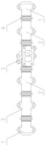
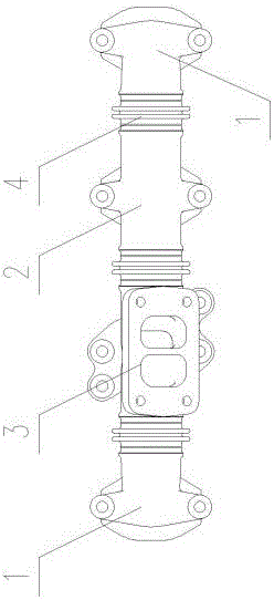
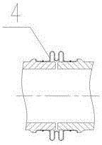
[0016] Multi-stage exhaust pipe structure, including end exhaust pipes 1 located on both sides of the array, several sections of intermediate exhaust pipes 1 are arranged between the two end exhaust pipes 1), and the two end exhaust pipes 1 Also be provided with at least one supercharging exhaust pipe 3 between, on the wall surface of described supercharging exhaust pipe 3, be provided with supercharger air outlet, described supercharging exhaust pipe 3 is arranged on any two adjacent Between the middle exhaust pipes 1, the terminal exhaust pipe 1, the middle exhaust pipe 1, and the booster exhaust pipe 3 are connected by metal bellows 4, and the terminal exhaust pipe 1, the middle exhaust pipe Both ends of the air pipe 1 and the supercharging exhaust pipe 3 are provided with an annular flange, and the axial ends of the metal bellows are pressed against the opposite surfaces o...


PUM


Abstract

The invention discloses a multi-segment type exhaust pipe structure. The multi-segment type exhaust pipe structure comprises tail-end exhaust pipes located at the two sides of an array. Multiple middle exhaust pipes are arranged between the two tail-end exhaust pipes. One or more pressurization exhaust pipes are further arranged between the two tail-end exhaust pipes. A pressurizer gas outlet is formed in the wall face of each pressurization exhaust pipe. Each pressurization exhaust pipe is arranged between every two adjacent middle exhaust pipes. The tail-end exhaust pipes, the middle exhaust pipes and the pressurization exhaust pipes are connected with one another through metal corrugated pipes. According to the multi-segment type exhaust pipe structure, the exhaust pipes are connected into a whole by welding the metal corrugated pipes; complete sealing is achieved at connection positions of the exhaust pipes; inter-pipe leakage of the exhaust pipes is completely eradicated; the metal corrugated pipes can extend and contract freely; the influence of thermal deformation of the exhaust pipes is eliminated; and damage to exhaust pipe gaskets is reduced, and thus the service life of each exhaust pipe gasket is prolonged.

Description

technical field [0001] The invention belongs to the technical field of engines, in particular to a multi-stage engine exhaust pipe structure. Background technique [0002] With the strengthening of engines and technology upgrades, the exhaust temperature, braking power and exhaust back pressure of commercial vehicle engines continue to increase, and the sealing performance of engine exhaust systems is facing the challenge of high temperature and high pressure. At present, most of the existing upright 6-cylinder commercial vehicle engine exhaust pipelines adopt a three-section structure, and the joints of the sections are sealed with a metal sealing ring and a ring groove. Sealing, and under high temperature and high pressure working conditions, its sealing performance is relatively poor. During the cold start of the engine, the blow-by phenomenon is more serious. Especially for medium-duty and heavy-duty commercial vehicle diesel engines, when the application of engine bra...

Claims


Application Information

Patent Timeline
Patent Type & Authority Applications(China)
IPC IPC(8): F01N13/08F01N13/18
Inventor 王一江徐卫国杨振国董佳孙瑞白刘军徐子喻
Owner CHINA FIRST AUTOMOBILE
Why Eureka
Try Eureka