
Radiating device of Stirling engine

A technology of Stirling engine and heat dissipation device, which is applied in hot gas variable capacity engine devices, engine components, machines/engines, etc., can solve problems such as serious energy loss, and achieve energy recovery, easy portability, and reliable and simple structure. Effect

Inactive Publication Date: 2017-05-10
GUILIN UNIV OF AEROSPACE TECH
View PDF6 Cites 0 Cited by
  • Summary
  • Abstract
  • Description
  • Claims
  • Application Information

AI Technical Summary

Problems solved by technology

The heat generation of medium and large equipment is more considerable, and its energy loss is suddenly more serious

Method used


Image

  • Radiating device of Stirling engine

Examples


Embodiment

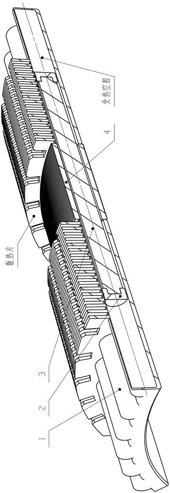
[0014] Such as figure 1 As shown, the heat dissipation device of the Stirling engine is composed of a cylinder block 1, a heat insulating ring 2, a magnetic bar 3 and a radiator 4, wherein: the cylinder block 1 is a symmetrically arranged hot cavity and a cold cavity, and are respectively connected with The magnetic bar 3 and the radiator 4 are connected, and the hot chamber and the cold chamber are connected through rods; the cylinder block 1 is filled with hydrogen or helium gas, and after cooling, compression, heat absorption, and expansion, a cycle of output power is formed, and The heat ring 2 is arranged symmetrically in the cylinder body 1 on both sides; the magnetic rod 3 is arranged in the middle of the two heat insulation rings 2; by heating the hot chambers on both sides of the symmetry, the pressure of the hot chamber and the cold chamber are different, Push the two insulation rings 2 to make a linear reciprocating motion under the guidance of the cylinder wall, so...


PUM


Abstract

The invention discloses a radiating device of a Stirling engine. The radiating device comprises air cylinder bodies, heat insulation rings, a magnetic bar and a radiator; the air cylinder bodies comprise hot cavities and cold cavities, and the hot cavities and the cold cavities are symmetrically arranged, connected with the magnetic bar and the radiator and connected through rod pieces; the heat insulation rings are symmetrically arranged in the air cylinder bodies on the two sides; the magnetic bar is arranged in the middles of the two heat insulation rings; the air cylinder bodies are filled with work media; a period of circulation output power is formed through cooling, compression, heat absorption and expansion; the two heat insulation rings are pushed to do back and forth movement linearly under cylinder wall guiding by heating the hot cavities symmetrically arranged on the two sides through the difference of the pressure of the hot cavities and the pressure of the cold cavities of the radiating device, so that the air cylinder bodies are in a dynamic equilibrium state of constant reciprocating linear movement, the magnetic bar also moves along with the air cylinder bodies, coils in the radiator are cut regularly, and the wave shape of the coils is regular relatively; and an electric current is generated, passes through a rectifying circuit and then is stored and reused.

Description

technical field [0001] The invention relates to the field of energy-saving electromechanical devices, in particular to a cooling device for a Stirling engine. Background technique [0002] The Stirling engine outputs power through a cycle of cooling, compressing, absorbing heat, and expanding the working medium (hydrogen or helium) in the cylinder, so it is also called a heat engine. [0003] The general heat dissipation device releases and consumes heat directly, whether it is heat sink, fan, water cooling, or liquid nitrogen cooling, there is basically no difference. The first two are to use the flowing air to take away the heat, and the latter two are to take away the heat by the liquid, and the other is to create a low-temperature environment to expect the heat to be lost quickly. However, no matter which one is used, the lost heat energy is not utilized, and the energy loss of mechanical and electronic equipment is inevitable, which is an objective law. The heat radia...

Claims


Application Information

Patent Timeline
IPC IPC(8): F02G1/055F02G1/053
CPCF02G1/055F02G1/053F02G2270/55
Inventor 张栋梁何雨桓刘飞
Owner GUILIN UNIV OF AEROSPACE TECH
Learn More