Engine group comprising a mixed fuel engine and fuel supplying method therof

An engine block and mixed fuel technology, applied in gaseous engine fuels, combustion engines, internal combustion piston engines, etc., can solve problems such as increased loss, economic infeasibility, and unsatisfactory

Inactive Publication Date: 2017-05-10
STMICROELECTRONICS SRL
View PDF4 Cites 28 Cited by
  • Summary
  • Abstract
  • Description
  • Claims
  • Application Information

AI Technical Summary

Problems solved by technology

However, to date, such research in this direction has never Energy point of view has proven to be unsatisfactory

Method used


Image

  • Engine group comprising a mixed fuel engine and fuel supplying method therof

Examples


Embodiment Construction

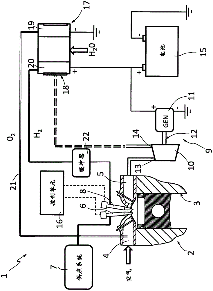
[0011] refer to figure 1 , numeral 1 generally represents the engine block of the vehicle (not shown).

[0012] The engine block 1 comprises an engine 2 with at least one cylinder 3 , an intake manifold 4 and an exhaust manifold 5 .

[0013] The engine 2 comprises a main injector 6 for each cylinder 3 connected to a system 7 for supplying a main fuel, for example methane or natural gas of known kind. Alternatively, any other conventional fuel, such as gasoline, diesel, LPG, biofuel, or mixtures thereof, can be used as the primary fuel.

[0014] The engine 2 further includes a secondary injector 8 for hydrogen-rich primary fuel for each cylinder 3, which will be described below.

[0015] The engine block 1 comprises a turbine generator 9 for recovering exhaust heat energy and converting it into electrical energy. The turbine generator 9 comprises a turbine 10 and a generator 11 rotatably connected to a rotor of the turbine 10 by a shaft 12 .

[0016] The turbine 10 has an i...


PUM


Abstract

An internal combustion engine is supplied with a mixed fuel from a supply system. The mixed fuel includes hydrogen. An electrolytic cell operates to produce hydrogen and oxygen starting from water in a liquid or vapor state. The produced hydrogen is delivered for inclusion in the mixed fuel and the produced oxygen is delivered to an intake of the internal combustion engine. A converter device operates to generate electrical energy starting from the thermal energy of exhaust gases output from the internal combustion engine. At least part of the electrical energy generated by the converter device is used in the electrolytic cell for the production of hydrogen.

Description

technical field [0001] The present invention relates to an engine block comprising a mixed fuel internal combustion engine, in particular to an internal combustion engine using conventional fuel rich in hydrogen. The invention also relates to a method for supplying the aforementioned internal combustion engine. Background technique [0002] It is well known that in the automotive industry there is an urgent need to reduce pollutant emissions. One of the routes taken to achieve this is to provide hydrogen-rich conventional fuels, such as methane or natural gas. [0003] It is further known that producing usable hydrogen on motor vehicles is problematic. [0004] According to a first known technique, hydrogen can be stored in vehicles in specially provided tanks in the form of liquid or compressed gas. However, the difficulty of hydrogen management and the lack of network assurance provided make this option commercially unattractive. [0005] Another known possibility is t...

Claims


Application Information

Patent Timeline
Patent Type & Authority Applications(China)
IPC IPC(8): F02M25/12F01N5/02F01D15/10
CPCF01D15/10F01N5/02F02M25/12F01N5/04F02B43/10F02B2043/106Y02T10/12Y02T10/30F02G5/02H02K7/1823
Inventor P·克雷马
Owner STMICROELECTRONICS SRL
Why Eureka
Try Eureka