Novel wave power generation device

A power generation device and wave energy technology, which is applied to ocean energy power generation, engine components, machines/engines, etc., can solve the problems of low reliability, different emphases, and low efficiency of wave energy conversion, so as to avoid seawater corrosion and improve Flexibility, the effect of reducing energy loss

Inactive Publication Date: 2017-05-10
OCEAN UNIV OF CHINA
8 Cites 8 Cited by

AI-Extracted Technical Summary

Problems solved by technology

Since these problems should be considered in the process of converting wave energy into electric energy, it leads to different solutions with different emphases, resulting in the diversity and div...

Abstract

The invention discloses a novel wave power generation device, and belongs to the technical field of power generation equipment. The novel wave power generation device comprises a vibration floater, a mooring rope, a guide wheel, a linear generator, an underwater damping device and an elastic connection component, wherein the vibration floater is directly connected to the linear generator through the mooring rope and the elastic connection component, the linear generator is composed of a mover, a stator and a stator fixing frame, the linear generator is placed in the vibration floater in a sealed mode, and the vibration floater is flexibly connected to the underwater damping device. Under the excitation of waves, the vibration floater vibrates up and down and drives the mover of the linear generator to conduct rectilinear motion through the mooring rope, the movement of the mover makes magnetic flux in a stator coil change so as to generate induced electromotive force, and so that wave power generation is achieved. According to the novel wave power generation device, the problem that in the prior art, reliability and low efficiency are contradictory in a wave power generation device is solved, and the purpose that considerations are given to both reliability and high efficiency is achieved.

Application Domain

Technology Topic

Image

  • Novel wave power generation device
  • Novel wave power generation device

Examples

  • Experimental program(2)

Example Embodiment

[0017] Example 1
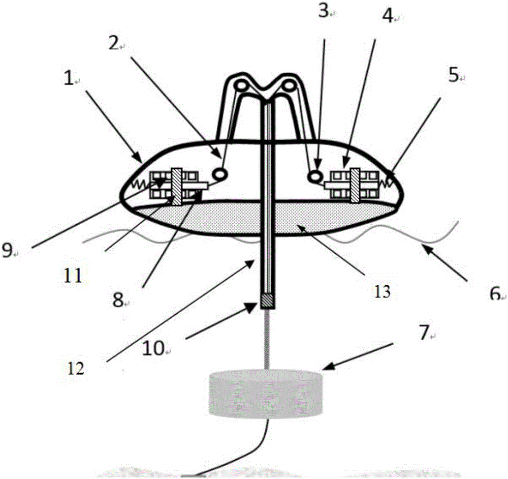
[0018] like figure 1 As shown, the linear generator 4 is directly sealed and placed inside the oscillating float 1. The material of the oscillating float is ordinary carbon structural steel (Q235). The linear generator 4 is composed of a mover 8, a stator 9 and a stator fixing frame 11. The frame 11 is fixed inside the oscillating float 1 by bolts, one end of the mover 8 of the linear generator 4 is connected with the oscillating float 1 through a spring 5, and the other end of the mover 8 of the linear generator 4 passes through the guide wheel 3 and the underwater The damping device 7 is connected, and there are 4 guide wheels 3, the positions of which are as follows: figure 1 As shown, the underwater damping device 7 is fixed underwater by the cable 2, and is flexibly connected with the oscillating float 1. In order to prevent water from intruding into the oscillating float 1 and ensure the sealing effect, a cable channel 12 placed in the water is provided at one end of the cable movement channel. The sealing ring 10, the inside of the oscillating float 1 is filled with a very low-density foam filler 13.
[0019] Under the excitation of the wave 6, the oscillating float 1 vibrates up and down, and the mover 8 of the linear generator 4 is driven to reciprocate linearly in the direction parallel to the horizontal plane through the cable 2. The stator 9 is fixed on the stator fixing frame 11 to maintain a relatively static state. The movement of 8 changes the magnetic flux in the coil of stator 9 to generate induced electromotive force to realize power generation.

Example Embodiment

[0020] Example 2
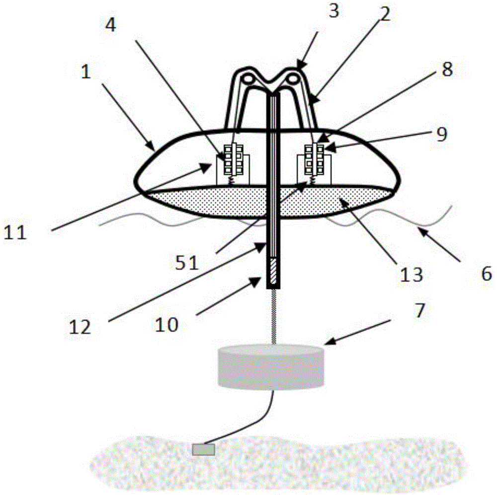
[0021] like figure 2 As shown, it is another embodiment of the present invention, the moving direction of the mover 8 of the linear generator 4 is set to be perpendicular to the horizontal plane, the number of three guide wheels is set to two, and the position is as follows figure 2 As shown, one end of the mover 8 of the linear generator 4 is connected with the oscillating buoy 1 through a rubber band 51 . Under the excitation of the wave 6, the oscillating float 1 vibrates up and down, and drives the mover 8 of the linear generator 4 to perform a reciprocating linear motion through the cable 2. The mover 8 moves perpendicular to the horizontal plane, and the stator 9 is fixed on the stator fixing frame 11 for maintenance. Relative to the static state, the movement of the mover 8 changes the magnetic flux in the coil of the stator 9 to generate an induced electromotive force to realize power generation.

PUM

no PUM

Description & Claims & Application Information

We can also present the details of the Description, Claims and Application information to help users get a comprehensive understanding of the technical details of the patent, such as background art, summary of invention, brief description of drawings, description of embodiments, and other original content. On the other hand, users can also determine the specific scope of protection of the technology through the list of claims; as well as understand the changes in the life cycle of the technology with the presentation of the patent timeline. Login to view more.

Similar technology patents

Integrated electro-hydraulic servo driver hydraulic system

Owner:THE GENERAL DESIGNING INST OF HUBEI SPACE TECH ACAD

Classification and recommendation of technical efficacy words

  • Reduce energy loss
  • Prevent seawater corrosion

High-precision maximum power point tracing method

ActiveCN101651436AOvercoming misjudgmentReduce energy lossPV power plantsPhotovoltaic energy generationObservation methodMppt algorithm
Owner:SUNGROW POWER SUPPLY CO LTD

Lube Base Oil, Process for Production Thereof, and Lubricating Oil Composition

ActiveUS20100041572A1High level of functionReduce energy lossTin organic compoundsGroup 5/15 element organic compoundsIodine valueEnergy loss
Owner:NIPPON OIL CORP +1

Spherical pig receiving-sending device and method

ActiveCN103721987APrevent seawater corrosionSecurityHollow article cleaningSeawaterCorrosion
Owner:CHINA NAT OFFSHORE OIL CORP +2

Outer ship hull protective coating and application method thereof

ActiveCN107868523AImprove adhesion and corrosion resistancePrevent seawater corrosionVessel cleaningHullsDecomposerFiber coating
Owner:YANTAI UNIV
Why Eureka
Try Eureka