Coupling expanding sleeve

An expansion sleeve and shaft coupling technology, applied in the field of coupling expansion sleeves, can solve the problems of increasing the volume of the coupling, cumbersome operation, and plastic deformation of the coupling components, so as to ensure dynamic balance, reduce the contact area, and reduce the pressing force. consistent effect

Inactive Publication Date: 2017-05-10
GUANGZHOU ACCUGLEN INTELLIGENT TECH LTD
View PDF5 Cites 1 Cited by
  • Summary
  • Abstract
  • Description
  • Claims
  • Application Information

AI Technical Summary

Problems solved by technology

Since the existing coupling scheme requires two connecting pieces to be connected to the drive shaft and the driven device respectively, this increases the volume of the coupling itself
At the same time, the two connecting parts of the coupling respectively connecting the drive shaft and the driven device need to be tightly connected to realize the transmission from the drive shaft to the driven device, which requires a certain amount of installation and operation space
thus causing a lot of wasted space
[0005] 2. Complex structure and high production cost
The existing coupling scheme contains many components, and the components may not be common for the corresponding drive shaft and driven device, which increases the cost of production and inventory
[0006] 3. Bad fit
However, due to the limitation of actual processing capacity, it is easy to cause inconsistencies in the pressing force of various parts between the coupling and the drive shaft
Moreover, the coaxial linkage between the drive shaft and the driven device cannot be achieved, which makes the device easy to lose dynamic balance and generate strong vibration, and the transmission accuracy is not high
[0007] 4. Inconvenient installation
In the adjustment process, the actions of loosening and locking the fasteners will be repeated, and the operation is very cumbersome.
Moreover, once repeated installation occurs, it is very easy to cause plastic deformation of the coupling assembly, affecting transmission accuracy and dynamic balance

Method used


Image

  • Coupling expanding sleeve
  • Coupling expanding sleeve
  • Coupling expanding sleeve

Examples


Embodiment 1

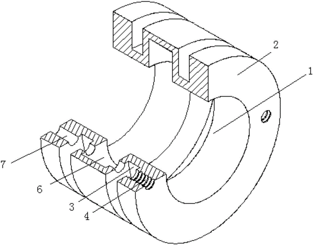
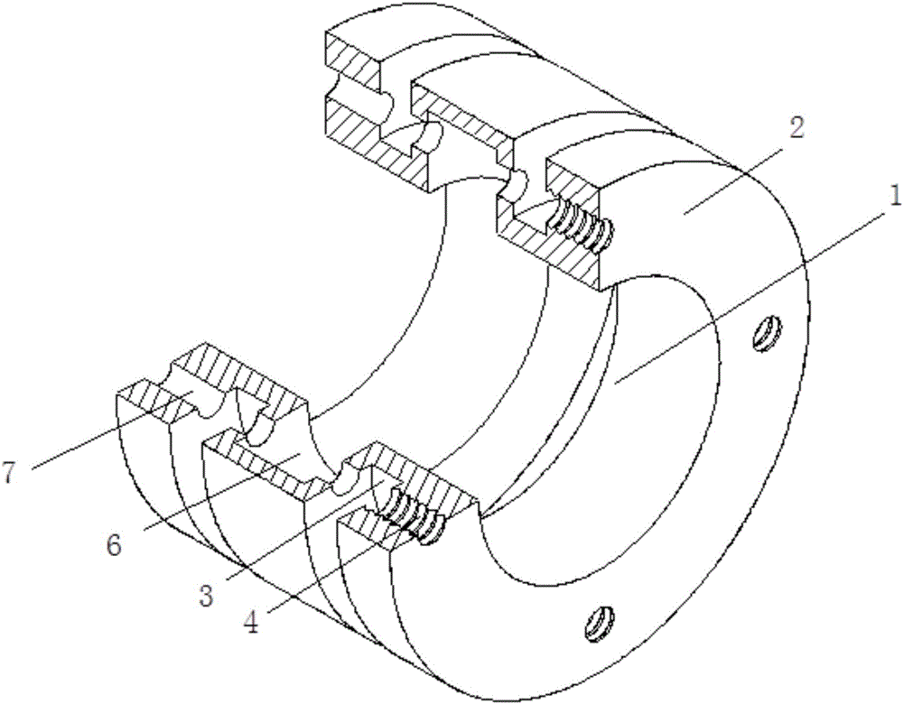
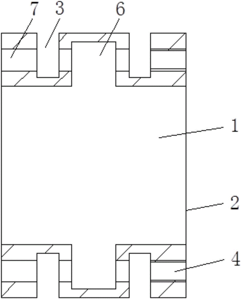
[0026] like Figure 1-5 As shown, a coupling expansion sleeve, the longitudinal section of the coupling expansion sleeve is in the shape of a square wave, including a cylinder 2 with a central shaft hole 1 and a screw 5, the cylinder 1 is provided with an outer annular groove 3, which is provided with an outer annular groove 3. The annular groove 3 is because to maintain a certain strength, the coupling expansion sleeve can be deformed, squeeze the driving shaft 111 and the driven shaft 112, so as to achieve the purpose of tightening transmission, the cylinder 2 is provided with a through hole in the axial direction. 7 and screw hole 6, the screw 5 is screwed into the screw hole 6 through the through hole 7, the diameter of the through hole 7 is larger than the diameter of the screw hole 6, the screw hole 6 is only located at the outer end of the outer annular groove 3, and the through hole 7 passes through In other parts of the cylinder 2, the arrangement of the through holes...

Embodiment 2

[0029] like Figure 1-5 As shown, a coupling expansion sleeve, the longitudinal section of the coupling expansion sleeve is a square wave shape, including a cylinder 2 with a central shaft hole 1, the cylinder 1 is provided with an outer annular groove 3, which is provided with an outer annular groove 3 It is because the coupling expansion sleeve can be deformed while maintaining a certain strength, and the driving shaft 111 and the driven shaft 112 can be squeezed, so as to achieve the purpose of tightening transmission. The cylinder 2 is axially provided with a through hole 7 and a screw. Hole 6, the screw 5 is screwed into the screw hole 6 through the through hole 7, the diameter of the through hole 7 is larger than the diameter of the screw hole 6, the screw hole 6 is only located at the outer end of the outer annular groove 3, and the through hole 7 passes through the cylinder 2 In other parts, the setting of the through hole 7 is convenient for tightening the screw 5, an...


PUM


Abstract

The invention discloses a coupling expanding sleeve. The coupling expanding sleeve comprises a column body with a central shaft hole and a screw, wherein the column body is provided with an external annular groove; the column body is provided with a through hole and a screw hole in the axial direction; and the screw is screwed into the screw hole through the through hole. The coupling expanding sleeve is simple in structure and convenient to mount, and is applicable to requirements of different specifications, different torque forces and high-precision axial concentric installation.

Description

technical field [0001] The invention relates to a coupling expansion sleeve. Background technique [0002] Couplings are widely used in the transmission of torque and motion between shafts and shafts or between shafts and rotating parts, and their characteristics are that they will not be separated from the shaft during the transmission process. In high-precision applications such as industrial robots, the coupling is required to have precision transmission and the ability to quickly and accurately adjust the axial concentricity of the drive shaft and the driven shaft to ensure the transmission accuracy and dynamic balance of the transmission process. The space between the driven shafts is limited, which in turn requires the coupling to have the characteristics of small size and convenient installation. Therefore, the disadvantages of the existing coupling structure are increasingly apparent. like Image 6 As shown, the existing coupling structure includes a first connecti...

Claims


Application Information

Patent Timeline
Patent Type & Authority Applications(China)
IPC IPC(8): F16D1/04
CPCF16D1/04
Inventor 艾鹰董俊阎素珍
Owner GUANGZHOU ACCUGLEN INTELLIGENT TECH LTD
Why Eureka
Try Eureka