Speed reducing chassis

A reduction box and box technology, which is applied in transmission boxes, components with teeth, gear lubrication/cooling, etc., can solve the problems of affecting the service life of the reducer, reducing the thermal power of the reducer, and poor cleanliness of lubricating oil. Achieve the effects of prolonging service life, reducing demand and increasing thermal power

Inactive Publication Date: 2017-05-10
天津市同仁铝压铸件有限公司
View PDF0 Cites 2 Cited by
  • Summary
  • Abstract
  • Description
  • Claims
  • Application Information

AI Technical Summary

Problems solved by technology

However, in general, the journal of the high-speed shaft is the thinnest, the corresponding bearing type is the smallest, and its lower end roller is the farthest from the bottom of the box body. Therefore, more lubricating oil is required in the reduction box to be higher than the lower end roller of the high-speed shaft, resulting in The heat balance temperature in the reducer box is relatively high, which reduces the thermal power of the reducer
When the existing reducer is in use, the gears mesh with each other to transmit power, and the gears wear each other. After the gears work for a long time, metal impurities such as iron filings will be produced. After a period of use, a large amount of metal impurities will be generated in the reducer box. Since the reducer adopts splash lubrication, iron filings will disperse to all corners of the reducer during the working process and travel with the lubricating oil inside the reducer, resulting in poor cleanliness of the lubricating oil, and the poor cleanliness of the lubricating oil will It will affect the work of the gears and bearings in the reducer box and affect the service life of the reducer

Method used


Image

  • Speed reducing chassis
  • Speed reducing chassis

Examples


Embodiment Construction

[0017] The preferred implementation modes provided by the present invention will be specifically described below in conjunction with the accompanying drawings.

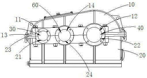
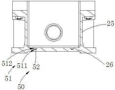
[0018] Figure 1 to Figure 2 , which is a preferred embodiment of a reduction box provided by the present invention. Such as Figure 1 to Figure 2 As shown, the reduction box includes an upper box body 10, a lower box body 20, a high-speed shaft installation hole 30, a low-speed shaft installation hole 40 and a chip collection assembly 50. The upper box body 10 is provided with a high-speed shaft upper half installation hole 11 and a low-speed shaft. The upper half mounting hole 12 of the shaft, the lower housing 20 is provided with the lower half mounting hole 21 of the high speed shaft and the lower half mounting hole 22 of the low speed shaft, the upper housing 10 fits the lower housing 20, the upper half mounting hole 11 of the high speed shaft is connected with the The lower half of the high-speed shaft mountin...


PUM


Abstract

The invention provides a speed reducing chassis. The speed reducing chassis comprises an upper box body, a lower box body, a high-speed shaft mounting hole, a low-speed shaft mounting hole and a chip collecting module; the upper box body is provided with a high-speed shaft upper half mounting hole and a low-speed shaft upper half mounting hole; the lower box body is provided with a high-speed shaft lower half mounting hole and a low-speed shaft lower half mounting hole; the upper box body is bonded with the lower box body; the high-speed shaft upper half mounting hole and the high-speed shaft lower half mounting hole form a high-speed shaft mounting hole; the low-speed shaft upper half mounting hole and the low-speed shaft lower half mounting hole form a low-speed shaft mounting hole; the set position of the high-speed shaft mounting hole corresponding to the bottom of the lower box body is lower than the set position of the low-speed shaft mounting hole; the chip collecting module includes a chip collecting tank and a magnet ring; the chip collecting tank is formed in the lower box body; and the magnet ring is mounted in the chip collecting tank. Compared with the prior art, the speed reducing chassis lowers the set position of the high-speed shaft mounting hole, reduces the lowest oil level of lubricating oil in a speed reducer, reduces the quantity demand of the lubricating oil, and meanwhile, is provided with the magnet ring for collecting free iron chips to prolong the service life of the speed reducer.

Description

technical field [0001] The invention relates to the field of reducers, in particular to a reducer box. Background technique [0002] The reducer is a kind of machine that divides the input power on the input shaft and decelerates it to meet the speed requirements of the next step. The reducer is generally used for low-speed and high-torque transmission equipment. The motor, internal combustion engine or other high-speed running power is used to achieve the purpose of deceleration through the gear with a small number of teeth on the input shaft of the reducer and the large gear on the output shaft. In order to reduce the friction of the internal gear of the reducer, oil-immersed lubrication is used in the reducer, and the minimum oil level of the lubricating oil should be higher than the lower end roller of the high-speed shaft. However, in general, the journal of the high-speed shaft is the thinnest, the corresponding bearing type is the smallest, and its lower end roller i...

Claims


Application Information

Patent Timeline
Patent Type & Authority Applications(China)
IPC IPC(8): F16H57/02F16H57/04
CPCF16H57/02F16H57/04
Inventor 刘哲学
Owner 天津市同仁铝压铸件有限公司
Why Eureka
Try Eureka