Spirally wound profile and spirally wound pipe

A spiral winding pipe and spiral winding technology, which is applied in the field of spiral winding profiles and spiral winding pipes, can solve the problems of difficult implementation of profile meshing methods, and achieve the effect of easy pipe thickness and no need for construction equipment

Inactive Publication Date: 2017-05-10
HUNAN DALU TECH CO LTD
View PDF10 Cites 1 Cited by
  • Summary
  • Abstract
  • Description
  • Claims
  • Application Information

AI Technical Summary

Problems solved by technology

[0005] The purpose of this application is to solve the problem that it is difficult to implem

Method used


Image

  • Spirally wound profile and spirally wound pipe
  • Spirally wound profile and spirally wound pipe
  • Spirally wound profile and spirally wound pipe

Examples


Embodiment 1

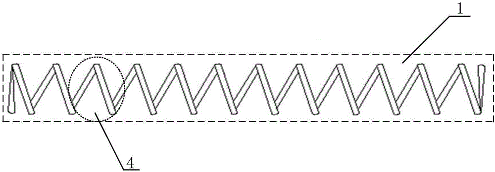
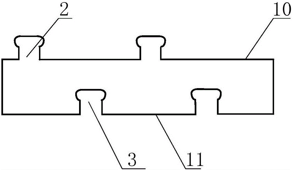
[0028] see figure 1 As shown, it is a front view of a helically wound profile provided by the application, including a helical profile body 1, see figure 2 As shown, it is a schematic cross-sectional structure diagram of the spirally wound profile provided by the present application. The spirally wound profile includes a clamping part 2, a clamping fitting part 3,

[0029] The clamping part 2 is arranged on the first side 10 of the profile body 1 along the radial direction, and the snap-fitting part 3 is arranged on the second side 11 of the profile body 1 along the radial direction;

[0030] Both the clamping part 2 and the clamping fitting part 3 extend along the spiral direction of the profile body 1;

[0031] The profile body 1 includes several integrally formed spiral profile rings 4 , and the adjacent spiral profile rings 4 are fixed by the clamping part 2 and the clamping fitting part 3 .

[0032] Further, the clamping part 2 is a convex part continuously arranged on...

Embodiment 2

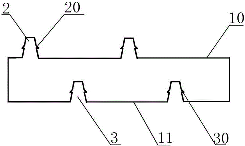
[0035] On the basis of embodiment 1, see image 3 As shown, it is a schematic diagram of an engagement structure of the clipping part 2 and the clipping fitting part 3 provided in the present application. The clamping part 2 is provided with a buckle 20, and the clamping fitting part 3 is provided with a clamping hole 30, and the buckle 20 cooperates with the clamping hole 30, thereby realizing the adjacent spiral profile circle 4 They are tightly fixed by the clamping part 2 and the clamping fitting part 3 .

Embodiment 3

[0037] On the basis of Embodiment 1, the difference from Embodiment 1 is that the snap-fit ​​part 2 is a raised part intermittently provided on the first side 10 of the profile body 1; the snap-fit ​​part 3 is a discontinuous The recessed part is provided on the second side 11 of the profile body 1; the opening end of the recessed part is flush with the second side 11, and the recessed part is engaged with the raised part.

[0038] Further, the protruding parts are T-shaped ribs arranged at equal or unequal intervals on the first side 10 of the profile body 1, and the recesses are arranged at equal or unequal intervals on the first side 10 of the profile body 1. T-shaped slots on two sides 11.


PUM


Abstract

The invention relates to the technical field of repair of conveying pipelines, in particular to a spirally wound profile and a spirally wound pipe. The profile comprises a spiral profile body, clamping parts and clamping matching parts; the clamping parts are arranged on the first side surface of the profile body in the radial direction; the clamping matching parts are arranged on the second side surface of the profile body in the radial direction; the clamping parts and the clamping matching parts extend in the spiral direction of the profile body; and the profile body comprises a plurality of integrally molded spiral profile coils. When a pipeline is repaired with the non-excavation technology, under the acting force of winding equipment, the adjacent spiral profile coils are fixed through the clamping parts and the clamping matching parts, the pipe is formed in situ through winding inside the pipeline, and then the whole to-be-repaired pipeline is repaired. Besides, in the non-excavation pipeline repair process, the profile is simple and convenient to construct, complex construction equipment is not required, and the application prospect is broad.

Description

technical field [0001] The present application relates to the technical field of pipeline repair, in particular to a spirally wound profile and a spirally wound pipe. Background technique [0002] Underground pipelines are closely related to people's daily life. They are one of the important infrastructures that support social development and ensure people's lives. They are the "lifeline" that cities rely on for survival and development. infrastructure. [0003] Underground pipelines will inevitably have cracks, leakage, corrosion and other phenomena during use, and these conditions seriously affect the normal function of the pipeline. The traditional excavation and repair technology uses excavation to replace or repair the pipeline, and its construction has a great impact on traffic, environment and social economy, especially in bustling urban areas; at the same time, it may also cause ground or underground damage around the pipeline. damage to structures. Therefore, the...

Claims


Application Information

Patent Timeline
IPC IPC(8): F16L55/162F16L9/16
CPCF16L55/162F16L9/16
Inventor 童设华孙赛武刘智峰湛文王蕾杨佳
Owner HUNAN DALU TECH CO LTD
Why Eureka
Try Eureka