
A device and method for burning coal slime in a large proportion in thermal power generation

A large-scale, slime technology, applied in the field of thermal power generation equipment, can solve the problems of impossibility of deflagration, vibration of coal slime pipeline, high pipe rack, etc., and achieve the effects of easy promotion and use, vibration prevention and simple structure

Active Publication Date: 2019-10-15
国投盘江发电有限公司
View PDF6 Cites 0 Cited by
  • Summary
  • Abstract
  • Description
  • Claims
  • Application Information

AI Technical Summary

Problems solved by technology

[0003] The coal slime produced by various coal washing plants is often piled together with gangue, which is inevitably mixed with stones and sundries. In the existing coal slime conveying system for thermal power generation, because there is no corresponding screening device, stones and sundries After the material enters the coal slime conveying system, it is easy to cause blockage, making it difficult for the normal and continuous transportation of the coal slime
In addition, in the existing coal slime conveying system, the coal slime pipeline is unreasonably fixed, there are many elbows on the coal slime pipeline, and the pipe frame is high. Continuous delivery
Furthermore, in the existing thermal power boilers, the coal slime is directly transported into the furnace by pipes, and the deflagration of the coal slime in the furnace cannot be achieved by using this feed structure, resulting in a low proportion of coal slime mixed combustion, and it is impossible to achieve a large proportion of coal slime Blending

Method used


Image

  • A device and method for burning coal slime in a large proportion in thermal power generation
  • A device and method for burning coal slime in a large proportion in thermal power generation
  • A device and method for burning coal slime in a large proportion in thermal power generation

Examples


Embodiment Construction

[0026] Below in conjunction with accompanying drawing and specific embodiment the invention is further introduced:

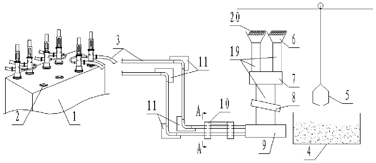
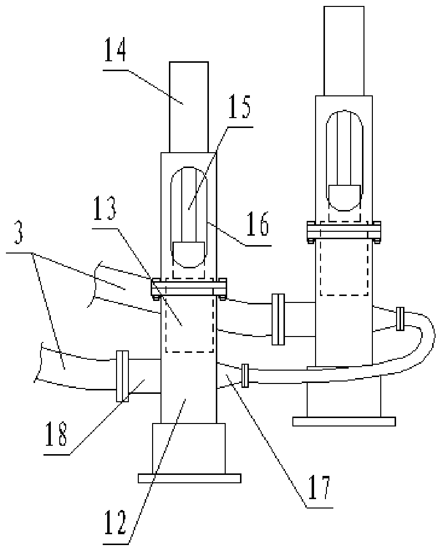
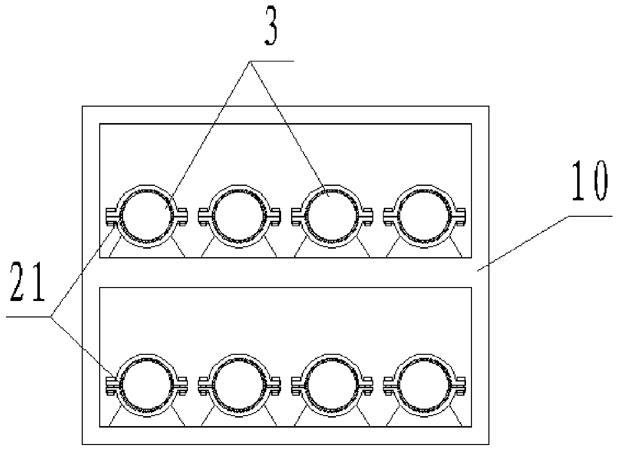
[0027] A device for blending coal slime in a large proportion in thermal power generation, comprising a furnace body 1 and a slime pool 4, a hopper 6 is arranged on one side of the slime pool 4, an agitator 7 is arranged below the hopper 6, and the agitator 7 The plunger pump 9 is arranged below the hopper, the hopper 6 and the agitator 7 and between the agitator 7 and the plunger pump 9 are respectively connected by a vertical drop pipe 19, and a coal slime grate 20 is arranged at the mouth of the hopper 6 ,Such as Figure 4 Shown, coal slime grate 20 adopts the grid structure that steel bar is welded. On the falling pipe 19 between the agitator 7 and the plunger pump 9, a vibrating screen 8 is arranged, and a plurality of coal slime inlets 2 are arranged on the top of the body of heater 1 to communicate with the hearth of the body of heater 1, and each coal s...


PUM


Abstract

The invention discloses a large-proportion coal slime blending combustion device for thermal power generation. The device comprises a furnace and a coal slime pond. Hoppers are arranged on one side of the coal slime pond, a stirrer is arranged under the hoppers, a plunger pump is arranged below the stirrer, the hoppers are connected with the stirrer through vertical falling tubes, and the stirrer and the plunger pump are connected through a vertical fall tube. A coal slime grate is arranged on an opening of each hopper, a vibrating screen is arranged on the falling tube between the stirrer and the plunger pump, and a plurality of coal slime inlets are formed in the top of the furnace and communicate with a hearth of the furnace; and a piston pushing mechanism is arranged on each coal slime inlet, and each piston pushing mechanism is connected with the plunger pump through a conveying pipeline. The coal slime grates and the vibrating screen are used for conducting double screening on coal slime, blocking caused by stone and impurities in the coal slime is prevented, and the coal slime can be normally and continuously conveyed; and through the piston pushing mechanisms, the cylindrical coal slime enters the hearth and detonates, and large-proportion coal slime blending combustion is achieved.

Description

technical field [0001] The invention relates to a device for blending coal slime with a large proportion in thermal power generation, and belongs to the technical field of thermal power generation devices. Background technique [0002] Coal slime is the main by-product in the coal washing process. It has the characteristics of high moisture content, high ash content, fine particles, high viscosity, strong water holding capacity, strong cohesive force, and difficult transportation, which brings a lot of inconvenience to the comprehensive utilization of coal slime. At present, in order to reduce the power generation cost of coal-fired power plants, coal slime is often used as a blended fuel, which is burned in the furnace body together with raw coal. [0003] The coal slime produced by various coal washing plants is often piled together with gangue, which is inevitably mixed with stones and sundries. In the existing coal slime conveying system for thermal power generation, bec...

Claims


Application Information

Patent Timeline
Patent Type & Authority Patents(China)
IPC IPC(8): F23K1/00F23K3/00
Inventor 张平尹利生陈诗春李荣伟刘实樊家亮
Owner 国投盘江发电有限公司
Learn More