

Humidifier
A humidifier and water tank technology, applied in air humidification systems, heating methods, lighting and heating equipment, etc., can solve the problems of high processing cost, high cost, high noise, etc., and achieve the effect of simple structure, low cost, and easy water addition.
- Summary
- Abstract
- Description
- Claims
- Application Information
AI Technical Summary
Problems solved by technology
Method used
Image

Examples
Embodiment 1
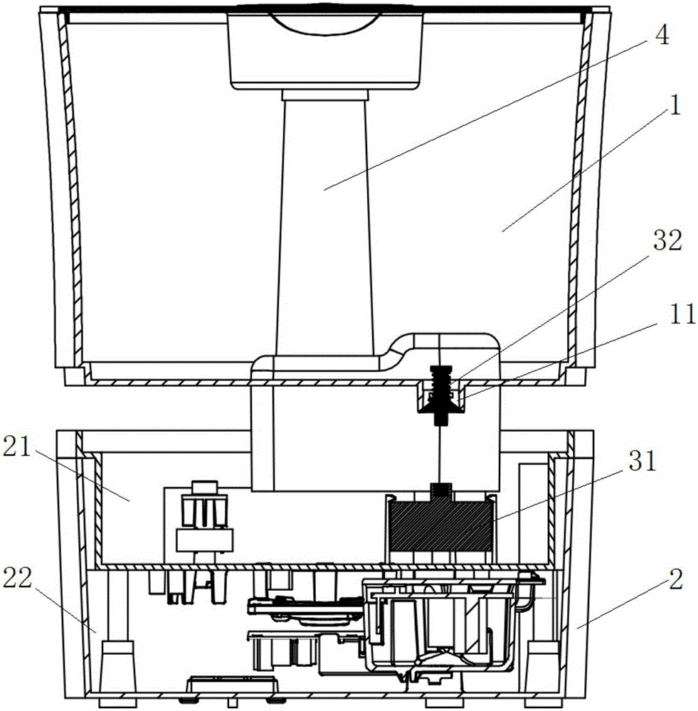
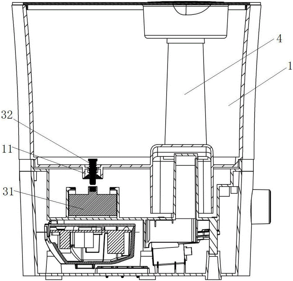
[0064] This embodiment provides a humidifier. The humidifier in this embodiment is a humidifier with water added from above. Specifically, as Figure 1 to Figure 5 As shown, the humidifier in this embodiment includes a water tank assembly 2, a water tank 1 and a water level control device. Wherein, the sink assembly 2 includes a base 22 and a sink 21 disposed on the base 22 . The water tank 1 is installed on the water tank 21, wherein the upper end of the water tank 1 is provided with a water inlet for filling water into the water tank 1; The water level control device includes a float device 31 arranged in the water tank 1 and a water level control switch 32 arranged at the water outlet 11 . Wherein, when the water level in the water tank 21 is lower than the set working water level, under the interaction of the float device 31 and the water level control switch 32, the water level control switch 32 is opened to the water outlet 11; when the water level in the water tank 21 ...
Embodiment 2
[0067] Preferably, this embodiment provides a humidifier, compared with the previous embodiment, such as Figure 1 to Figure 5 As shown, both the float device 31 and the water level control switch 32 in this embodiment are magnetic, and there is a magnetic attraction force between the float device 31 and the water level control switch 32 . In addition, the interaction between the float device 31 and the water level control switch 32 described in the previous embodiment refers to the mutual magnetic attraction.
[0068] Preferably, in this embodiment, the buoyant device 31 is designed as the following structure: Figure 8 , Figure 10 and Figure 11 As mentioned above, the float device 31 in this embodiment includes a float 311 and a first magnet 312 . Wherein, the first magnet 312 is arranged on the upper end of the float 311 for generating magnetic attraction to the water level control switch 32 . By setting in this way, the structure of the buoy device 31 is simple and t...
Embodiment 3
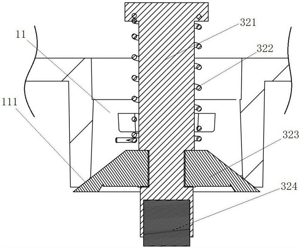
[0072] Preferably, this embodiment provides a humidifier. On the basis of Embodiment 2, the structural design of the water level control switch in this embodiment is as follows: figure 2 , Figure 12 to Figure 15 As shown, the water level control switch in this embodiment mainly includes: a valve core 321 , a spring 322 , and a valve body 323 . Wherein, the lower end of the valve core 321 is provided with a second magnet 324, and the magnetic pole of the second magnet 324 is opposite to that of the first magnet, and has magnetic attraction force. The spring 322 is sleeved on the valve core 321, and one end of the spring 322 is fixed to the valve core 321, and the other end is fixed to the water tank, so as to apply an upward elastic force to the water level control switch. The valve body 323 is sleeved on the valve core 321 , and the valve body 323 is used to block the drain port 11 . Wherein, the water level control switch can move up and down, and when the water level con...
PUM
 Abstract
Description
Claims
Application Information