A Method for Measuring Lateral Offset of Roadheader

A measurement method and lateral offset technology, which are used in measurement devices, radio wave measurement systems, earth-moving drilling, etc., can solve the problems of reducing reflection utilization, small receiving range, and difficulty in receiving laser signals to prevent excessive deviation. Effects that affect measurement results

Active Publication Date: 2019-01-01
CHONGQING HUAYU HEAVY IND ELECTROMECHANICAL CO LTD
View PDF4 Cites 0 Cited by
  • Summary
  • Abstract
  • Description
  • Claims
  • Application Information

AI Technical Summary

Problems solved by technology

In the current measurement method, the receiving range of a single reflective surface is half of the width of the roadway, and the receiving range is small, which is prone to the phenomenon that the laser misses the target during measurement. At the same time, there is an edge at the junction of the two reflective surfaces, and the laser will produce a diffuse emission effect here. , which greatly reduces the utilization rate of reflection, and it is difficult to receive laser signals, resulting in incomplete measurement coverage, which is easy to cause part of the measurement data to be lost

Method used


Image

  • A Method for Measuring Lateral Offset of Roadheader
  • A Method for Measuring Lateral Offset of Roadheader
  • A Method for Measuring Lateral Offset of Roadheader

Examples


Embodiment 1

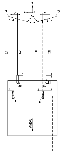
[0032] Embodiment 1: as figure 2 and image 3 As shown, a method for measuring the lateral offset of a roadheader in this embodiment includes the following steps:

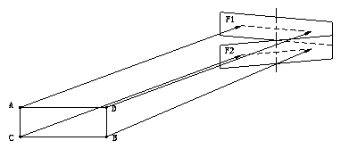
[0033] 1) Install two independent reflective surfaces F1 and F2 at the initial calibration point of the roadway, where the reflective surfaces F1 and F2 are independent vertical planes, and the length directions of the reflective surfaces F1 and F2 are located in the horizontal direction and match the width of the roadway. The centerlines of the reflective surfaces F1 and F2 are located on the central line of the roadway section, and the reflective surfaces F1 and F2 intersect up and down to form a certain angle θ;

[0034] 2) Install laser rangefinder A, laser transmitter D, laser rangefinder B, and laser transmitter C respectively on the roadheader corresponding to the two reflecting surfaces F1 and F2, where laser rangefinder A and laser transmitter D are located at the same Height, laser rangefinder B and la...
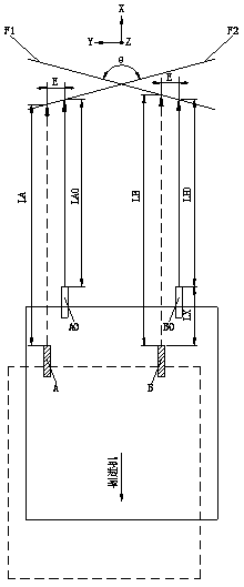
Embodiment 2

[0041] Embodiment 2: as figure 2 and Figure 4As shown, the laser rangefinder D, laser transmitter A, laser rangefinder C, and laser transmitter B are respectively installed on the roadheader corresponding to the two reflecting surfaces F1 and F2, wherein the laser rangefinder D and laser transmitter A are located at In the same horizontal plane, laser range finder C and laser transmitter B are located in the same horizontal plane, laser range finder D and laser transmitter B are located in the same vertical plane parallel to the roadway axis, laser range finder C and laser transmitter A is located in the same vertical plane parallel to the axis of the roadway, and the laser range finder D and laser range finder C are located in the same vertical plane perpendicular to the axis of the roadway. In the initial position, the distance between the laser range finder D and the reflecting surface F1 The distance between the laser range finder C and the reflective surface F2 is LC0,...


PUM


Abstract

The invention discloses a method for measuring the lateral shift of a tunneling machine. The method comprises the following steps: 1) installing two independent vertical flat reflecting surfaces F1 and F2 at an initial calibration point in a tunnel, wherein the vertical flat reflecting surfaces F1 and F2 intersect up and down to form a certain angle [theta], and the length directions of the vertical flat reflecting surfaces F1 and F2 are located in the horizontal direction and match the width of the tunnel; 2) installing a laser range finder A and a laser range finder B on the tunneling machine and at different heights to measure the distance between the two vertical flat reflecting surfaces F1 and F2 separately; 3), creating a three-dimensional coordinate; 4) monitoring the support distance LX of the tunneling machine in a support process, wherein the distance between the laser range finder A and the reflecting surface F1 is LA, and the distance between the laser range finder B and the reflecting surface F2 is LB; and 5) enabling a tunneling machine controller to automatically correct a trajectory in real time according to the shift direction and the shift distance measured in the step 4). The method is not liable to easy miss the target and wide in coverage.

Description

technical field [0001] The invention relates to the technical field of position and posture detection of a roadheader, in particular to a method for measuring the lateral offset of a roadheader. Background technique [0002] With the development of mine roadheader control technology, at present, remote control roadheader has gradually become an emerging intelligent coal mining machinery. The position and orientation measurement of the roadheader in the mine has become the basis of the research on the control system of the remote control roadheader. [0003] Taking the forward direction of the roadheader as the positive direction of the X axis, the horizontal direction perpendicular to the X axis to the right as the positive direction of the Y axis, and the vertical upward direction as the positive direction of the Z axis to establish a roadway coordinate system, the pose parameters of the roadheader are composed of four single factor Composition: yaw angle, roll angle, pitc...

Claims


Application Information

Patent Timeline
Patent Type & Authority Patents(China)
IPC IPC(8): G01S17/08G01S7/48G01S7/497E21D9/00
CPCE21D9/003G01S7/4808G01S7/4972G01S17/08
Inventor 吴忠保任艳军宋志忠韦易
Owner CHONGQING HUAYU HEAVY IND ELECTROMECHANICAL CO LTD
Why Eureka
Try Eureka