
A device capable of diagnosing a failure of a visibility sensor and a detection method

A sensor failure and visibility technology, applied in the direction of instruments, measuring devices, scientific instruments, etc., can solve the problems of high manpower investment and time-consuming, and achieve high automation, convenient use and maintenance, and good on-site use effect

Active Publication Date: 2022-06-24
ZHONGHUAN TIG TIANJIN METEOROLOGICAL INSTR
View PDF0 Cites 0 Cited by
  • Summary
  • Abstract
  • Description
  • Claims
  • Application Information

AI Technical Summary

Problems solved by technology

Therefore, the conventional method does not consume time and much manpower input.

Method used


Image

  • A device capable of diagnosing a failure of a visibility sensor and a detection method
  • A device capable of diagnosing a failure of a visibility sensor and a detection method
  • A device capable of diagnosing a failure of a visibility sensor and a detection method

Examples


Embodiment Construction

[0025] The present invention will be further described below in conjunction with accompanying drawing:

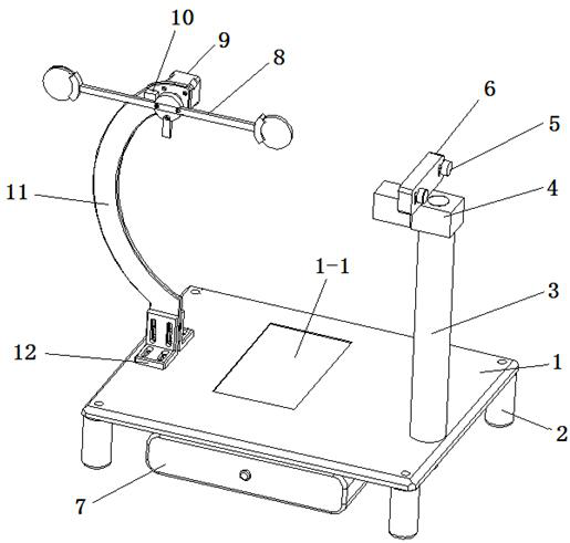
[0026] refer to Figure 1 to Figure 4 As shown, a device capable of diagnosing the failure of a visibility sensor includes a limit switch 10, a stepper motor 9, a chassis 1, a support column 2, a column 3, a cross arm 4, a knurled screw 5, a holding plate 6, and a control Box 7, detection device 8, motor support 11, fixed foot 12.

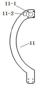
[0027] The motor support 11 is sickle-shaped and made of metal material. A motor hole 11-1 and a limit switch hole 11-2 are respectively arranged on the motor support 11 .

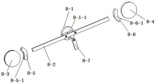
[0028] The detection device 8 includes a turntable 8-1, a frame cross arm 8-2, a circular detection lens A8-3, a circular detection lens B8-4, a lens holder A8-5, a lens holder B8-6, a limit horizontal Arms 8-7.

[0029] The frame cross arm 8-2 is screw mounted in the strip groove 8-1-1 on one side of the turntable 8-1, the limit cross arm 8-7 is screw mounted on the turn...


PUM


Abstract

The invention relates to a meteorological measuring instrument, in particular to a device capable of diagnosing a failure of a visibility sensor and a detection method. Mainly for the diagnosis of the visibility sensor, the equipment includes limit switches, stepping motors, chassis, support columns, columns, cross arms, holding plates, control boxes, detection devices, motor brackets, and fixed feet. The detection device is driven to rotate by the stepping motor, so that the detection device sequentially covers the laser detection area of ​​the measured visibility sensor, and the measured visibility sensor uploads the captured meteorological visibility status data to the host computer software. The host computer software compares the visibility difference of different detection devices with the standard deviation, and judges whether the measured visibility sensor is faulty or not through the judgment of the measured data and the difference. The equipment has the advantages of high degree of automation, convenient operation and maintenance.

Description

technical field [0001] The invention relates to a meteorological measuring instrument, in particular to a device capable of diagnosing a failure of a visibility sensor and a detection method. Background technique [0002] Visibility sensor is a kind of meteorological instrument with high sensitivity and strict requirements. After the instrument usually works for a period of time, its accuracy should be tested. The conventional method is to send the visibility sensor to the national or provincial measurement unit, and use the visibility simulation test, which is a waste of time, manpower and financial resources. Usually the detection of the visibility sensor is mainly to manually block the receiving end lens of the visibility sensor and compare the performance of the sensor with the standard visibility sensor. Therefore, the conventional method does not consume much time and manpower. Contents of the invention [0003] The object of the present invention is to provide a k...

Claims


Application Information

Patent Timeline
Patent Type & Authority Patents(China)
IPC IPC(8): G01W1/18G01N21/17
CPCG01N21/17G01W1/18
Inventor 刘李徐之兴林弘扬王淳
Owner ZHONGHUAN TIG TIANJIN METEOROLOGICAL INSTR
Learn More