

Robot charging method and device
A charging method and robot technology, which can be applied to instruments, motor vehicles, transportation and packaging, etc., can solve the problems of low charging efficiency and long time consumption of robots, and achieve the effect of improving charging efficiency and improving efficiency.
- Summary
- Abstract
- Description
- Claims
- Application Information
AI Technical Summary
Problems solved by technology
Method used
Image

Examples
Embodiment 1
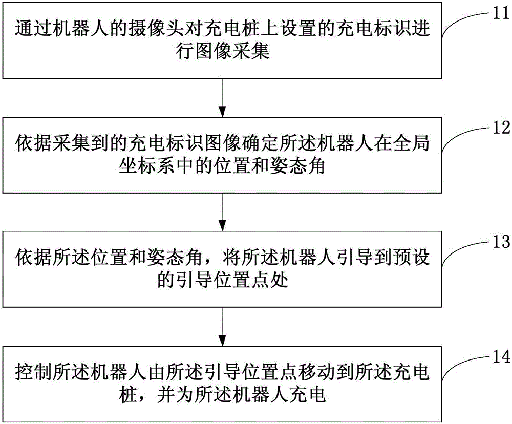
[0025] Figure 1a This is a flowchart of a robot charging method provided in the first embodiment of the present invention. The method in this embodiment may be executed by a robot charging device, which may be implemented in hardware and / or software. reference Figure 1a The robot charging method provided in this embodiment may specifically include the following:
[0026] Step 11. Use the camera of the robot to collect images of the charging signs set on the charging pile.
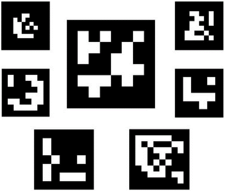
[0027] Figure 1b It is a schematic diagram of a charging identification provided in the first embodiment of the present invention, refer to Figure 1b In order to improve the detection effect of the charging mark, the charging mark can be black and white and contains n*n cell units, that is, the charging mark can be expressed as a matrix of 0 and 1, where 0 means black and 1 means white.
[0028] Specifically, the image collection of the charging sign by the camera set by the robot may include: acquiring the ima...
Embodiment 2
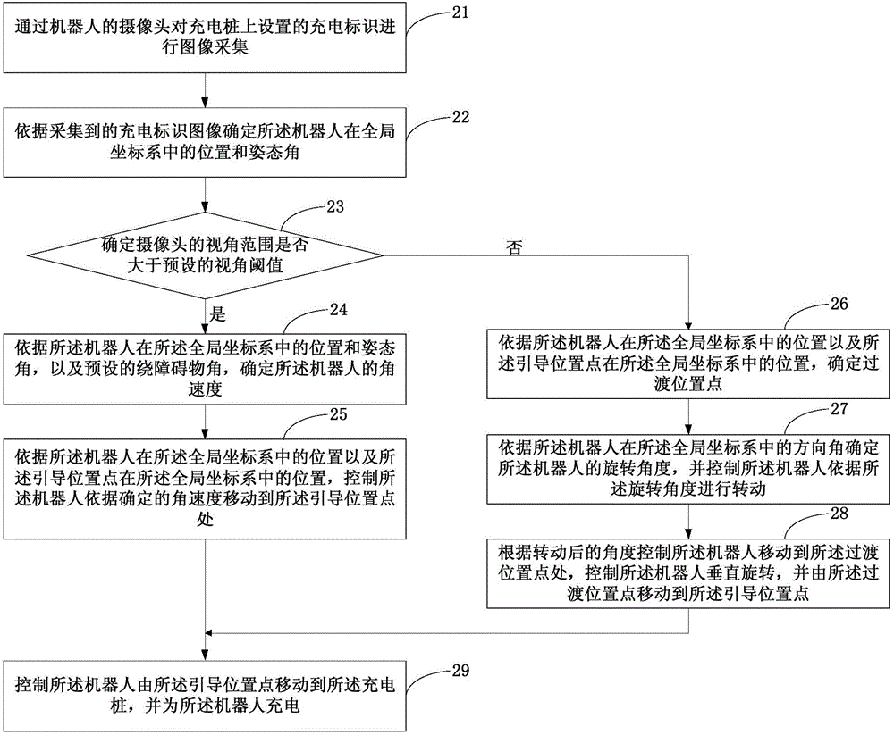
[0058] This embodiment provides a new robot charging method on the basis of the first embodiment above. Figure 2a This is a flowchart of a robot charging method provided in the second embodiment of the present invention. reference Figure 2a The robot charging method provided in this embodiment may specifically include the following:
[0059] Step 21: Use the camera of the robot to collect images of the charging signs set on the charging pile.
[0060] Step 22: Determine the position and posture angle of the robot in the global coordinate system according to the collected charging identification image.
[0061] Wherein, the global coordinate system takes the center point of the charging mark as the coordinate origin, the vertical plane of the plane where the charging mark is located is the xoy plane, and the vertical upward direction is the z axis.
[0062] Step 23: Determine whether the viewing angle range of the camera is greater than the preset viewing angle threshold, if it is gr...
Embodiment 3
[0087] This embodiment provides a new robot charging method on the basis of the first and second embodiments above. Figure 3a This is a flowchart of a robot charging method provided in the second embodiment of the present invention. reference Figure 3a The robot charging method provided in this embodiment may specifically include the following:
[0088] Step 31: Use the camera of the robot to collect images of the charging signs set on the charging pile.
[0089] Step 32: Determine the position and posture angle of the robot in the global coordinate system according to the collected charging identification image.
[0090] Wherein, the global coordinate system takes the center point of the charging mark as the coordinate origin, the vertical plane of the plane where the charging mark is located is the xoy plane, and the vertical upward direction is the z axis.
[0091] Step 33: Guide the robot to a preset guide position point according to the position and attitude angle.
[0092] Step...
PUM
 Abstract
Description
Claims
Application Information