
Eureka
For R&D, Eureka makes reading and utilizing patents & technical documents easy.
Eureka AIR
Designed for self-driven R&D workflows. Generate viable solutions, solve complex R&D challenges, empower your innovation with AI.

Eureka Materials
Designed for material experts only. Revolutionize your material R&D, from search, analyze, to developing new materials.

TechResearch
Generate reliable direction feasibility study reports for your R&D in just a few steps.

TechSeek
Discover and master advanced knowledge NOW. Basics, ideas, possibilities, all at once.

TechMind
As an expert in R&D Theories, TechMind can generates customized viable solutions instantly.

TechRisk
Analyze your overall solution with one click, know your potential R&D risks in advance.

TechMonitor
Get weekly tech updates, stay abreast of the latest tech innovations and key insights.
The host device of the two-bus communication circuit and the two-bus communication circuit
A two-bus communication and host device technology, applied in the field of communication, can solve problems such as electromagnetic clutter interference, increased circuit loss, and the failure of the host device to normally recognize the response signal of the slave device, so as to improve anti-interference ability and reduce loss Effect
- Summary
- Abstract
- Description
- Claims
- Application Information
AI Technical Summary
Problems solved by technology
Method used
Image

Examples
Embodiment 1
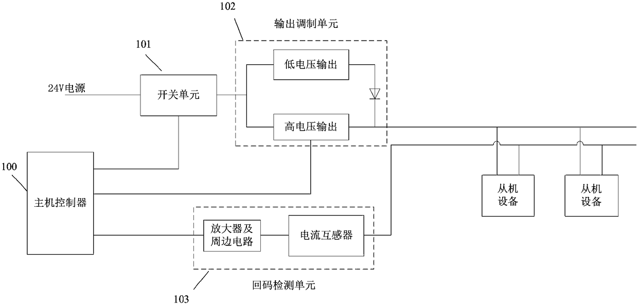
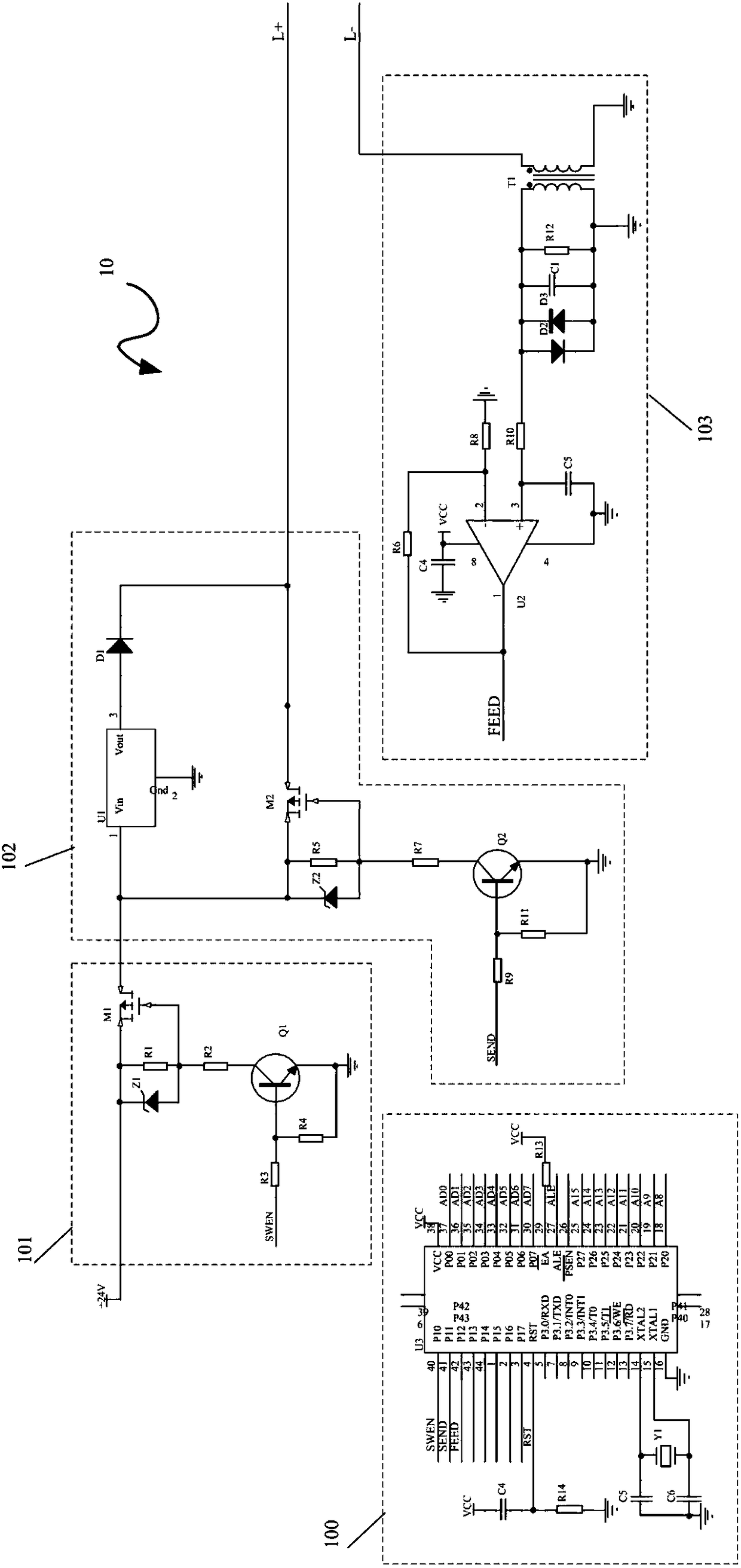
[0026] See Figure 1 to Figure 4 The host device 10 includes: a host controller 100, a switch unit 101, an output modulation unit 102, and a return code detection unit 103. The switch unit 101 is used to output a power supply voltage under the control of the host controller 100 and includes a control terminal, an input terminal and an output terminal. The input terminal of the switch unit 101 is connected to a power supply, and the control terminal of the switch unit 101 is connected to the host controller 100. The output modulation unit 102 is used to adjust the power supply voltage to the output voltage representing the communication data under the control of the host controller 100. The output setting time includes a control terminal, an input terminal and an output terminal. The control terminal of the output modulation unit 102 is connected to the host In the controller 100, the input terminal of the output modulation unit 102 is connected to the output terminal of the swit...
Embodiment 2
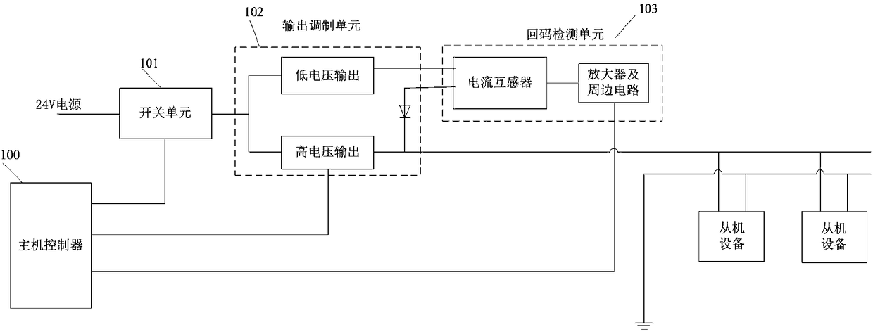
[0033] See Figure 1 to Figure 5 , The two-bus communication circuit of the present application includes: a host device 10 and at least one slave device 20, and the host device 10 is connected to the slave device 20 through the two buses.
[0034] The host device 10 includes: a host controller 100, a switch unit 101, an output modulation unit 102, and a return code detection unit 103. The switch unit 101 is used to output a power supply voltage under the control of the host controller 100 and includes a control terminal, an input terminal and an output terminal. The input terminal of the switch unit 101 is connected to a power supply, and the control terminal of the switch unit 101 is connected to the host controller 100. The output modulation unit 102 is used to adjust the power supply voltage to the output voltage representing the communication data under the control of the host controller 100. The output setting time includes a control terminal, an input terminal and an output...
PUM
 Abstract
Description
Claims
Application Information
 - R&D Engineer
- R&D Manager
- IP Professional
- Industry Leading Data Capabilities
- Powerful AI technology
- Patent DNA Extraction
Browse by: Latest US Patents, China's latest patents, Technical Efficacy Thesaurus, Application Domain, Technology Topic, Popular Technical Reports.
© 2024 PatSnap. All rights reserved.Legal|Privacy policy|Modern Slavery Act Transparency Statement|Sitemap|About US| Contact US: help@patsnap.com