Adaptive light compensation method based on projector-camera system

A projector and adaptive technology, applied in the field of adaptive optics, can solve problems such as unfavorable decision-making and execution, loss of detail information, etc., to achieve the effect of avoiding adverse effects and fast compensation processing speed

Inactive Publication Date: 2017-05-10
TIANJIN UNIV
View PDF1 Cites 4 Cited by
  • Summary
  • Abstract
  • Description
  • Claims
  • Application Information

AI Technical Summary

Problems solved by technology

[0003] However, most cameras have a limited 8-bit acquisition range due to limitations of charge-coupled devices and digital-to-analog conversion
When the measured scene has different parts with high reflectivity and low reflectivity, the collected image has only 8-bit pixel information. If the exposure is increased, the part with low reflectivity becomes clear, while the part with high reflectivity becomes Saturation; on the contrary, if the exposure is reduced, the part with high reflectivity will be clear, while the part with low reflectivity will become dark, so there will be extremely bright or dark areas for the part with high reflectivity or low reflectivity, resulting in detailed information loss, which will have an extremely adverse impact on subsequent decision-making and execution

Method used


Image

  • Adaptive light compensation method based on projector-camera system
  • Adaptive light compensation method based on projector-camera system
  • Adaptive light compensation method based on projector-camera system

Examples


Embodiment Construction

[0021] Below in conjunction with accompanying drawing and specific example the present invention will be further described;

[0022] In the adaptive light compensation of the present invention, the projector and the camera adopt a non-coaxial configuration, and for the convenience of subsequent calculation, the projector and the camera are placed on the same horizontal line. The distance between the projector and the camera is d, the distance from the projector to the reference plane is L, and the depth of the observation point O is h. Using the similarity principle of triangles, we have

[0023]

[0024] Represents the phase change, with

[0025]

[0026] Substituting formula (2) into formula (1), we get

[0027]

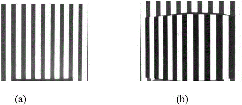
[0028] figure 1 Shown are the reference grating pattern and the distorted grating pattern in the present invention. The computer-generated sinusoidal grating stripes, such as figure 1 As shown in (a), when projected on the surface of a three-dimensi...


PUM


Abstract

The invention provides an adaptive light compensation method based on a projector-camera system. The method comprises the steps that a projector and a camera are placed on the same side of a screen and arranged in a non-coaxial mode, and the screen serves as a reference plane; a sinusoidal grating stripe is generated to serve as a reference stripe, the reference stripe is projected to the surface of a three-dimensional object through the projector, the reference stripe will be distorted under depth modulation, and the reference grating stripe and the distorted grating stripe are acquired through the CCD camera; the relation between object depth and stripe phase change is derived; Fourier transformation is utilized to extract fundamental components of a distorted grating and a reference grating from a frequency domain, then Fourier inverse transformation is utilized to transfer the extracted fundamental components back to a time domain, phases folded in the interval from -pi to pi are obtained, and the folded phases in discontinuous distribution are changed into decompressed phases in continuous distribution in space through a phase decompression algorithm; the decompressed phases are substituted into a phase and depth conversion formula to obtain the depth of each pixel point; images collected by the camera are processed.

Description

technical field [0001] The invention relates to an adaptive light compensation method based on a projector-camera system, belonging to the field of adaptive optics; Background technique [0002] Machine vision is playing an increasingly important role in quality inspection, process control, and 3D reconstruction. A typical machine vision system includes image capture, light source system, image digitization module, digital image processing module, intelligent judgment decision-making module and mechanical control execution module, the key technology of which is to analyze and process the acquired image accordingly, so the image The quality of the machine directly determines the accuracy of machine vision decision-making, and the quality of the acquired image depends on the image acquisition equipment and lighting equipment. [0003] However, most cameras have a limited 8-bit acquisition range due to limitations of charge-coupled devices and digital-to-analog conversion. Wh...

Claims


Application Information

Patent Timeline
Patent Type & Authority Applications(China)
IPC IPC(8): G06T7/80G01C11/04
CPCG01C11/04G06T2207/30204
Inventor 吕辰刚高爽方干鲍志强张帅
Owner TIANJIN UNIV
Why Eureka
Try Eureka