
High-voltage capacitor quasi-constant-power discharging apparatus with adjustable discharging power

A high-voltage capacitor, constant power discharge technology, applied in the direction of capacitors, liquid resistors, electrical components, etc., can solve the problems of large volume and weight of discharge devices, increased energy discharge time, and inability to adjust resistance online, and achieves a simple structure. , Easy installation, good discharge effect

Inactive Publication Date: 2017-05-10
NAT UNIV OF DEFENSE TECH
View PDF5 Cites 1 Cited by
  • Summary
  • Abstract
  • Description
  • Claims
  • Application Information

AI Technical Summary

Problems solved by technology

Due to the large discharge energy and high discharge voltage, multiple solid resistors are generally used in series and parallel to discharge as discharge resistors. However, in this case, a large number of resistors is required, and the volume and weight of the discharge device are large; The water resistor can be used as the discharge resistor for discharge. The water resistor has a large power capacity, so it is compact in size and light in weight, but there is also a problem. The resistance value of the current water resistor discharge device cannot be adjusted online, resulting in a very high initial discharge power. Large, and with the decrease of the capacitor voltage, in the later stage of discharge, the discharge current becomes significantly smaller, and the energy discharge time increases significantly

Method used


Image

  • High-voltage capacitor quasi-constant-power discharging apparatus with adjustable discharging power
  • High-voltage capacitor quasi-constant-power discharging apparatus with adjustable discharging power
  • High-voltage capacitor quasi-constant-power discharging apparatus with adjustable discharging power

Examples


Embodiment Construction

[0020] The preferred embodiments of the present invention will be described below in conjunction with the accompanying drawings. It should be understood that the preferred embodiments described here are only used to illustrate and explain the present invention, and are not intended to limit the present invention.

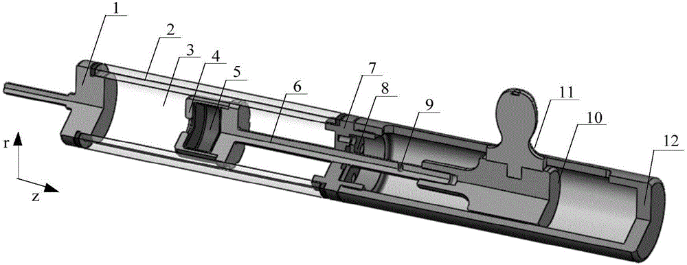
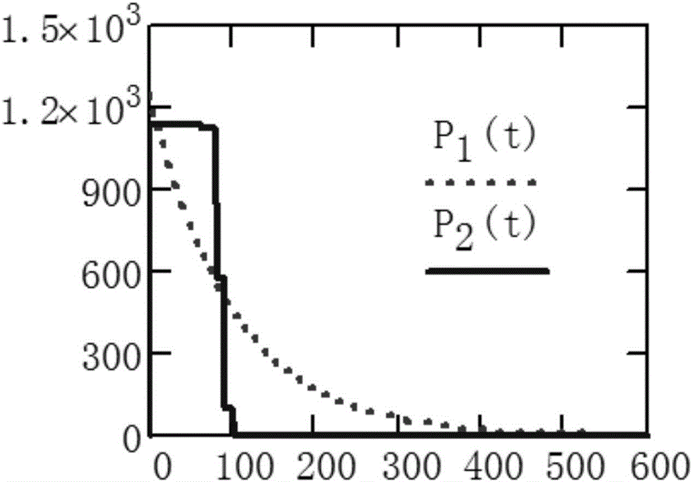
[0021] For specific implementation, see figure 1 and figure 2 , when the fully charged capacitor is in use, because the subsequent load device cannot work and energy discharge is required, the high-voltage discharge terminal 1 of the quasi-constant power discharge device is overlapped with the high-voltage terminal of the capacitor. At this time, the energy on the capacitor After passing through the discharge resistor 3 through the high-voltage discharge terminal 1, the energy is released to the ground through the low-voltage discharge terminal 4. The low-voltage discharge end 4 is connected to the ground potential through the grounding point 9 on the metal movabl...


PUM


Abstract

The invention belongs to the technical field of a high-power discharging apparatus, and specifically relates to a high-voltage capacitor quasi-constant-power discharging apparatus with adjustable discharging power. The discharging apparatus comprises a high-voltage discharging end (1), an organic glass outer cylinder (2), a discharging resistor (3), a low-voltage discharging end (4), a temperature compensation gasbag (5), a metal movable pull rod (6), a liquid resistor sealing plate (7), a sealing ring pressing plate (8), a low-voltage discharging end grounding point (9), a movable insulating supporting part (10), a liquid resistor adjusting handle (11) and an insulating supporting cylinder (12). The discharging resistor of the apparatus adopts the liquid resistor with adjustable resistance value; the discharging process comprises several time stages; and the discharging resistor is adjusted to an appointed numerical value at the beginning of each stage, so that approximately unchanged discharging power in the whole discharging time frame can be realized, the discharging time is greatly shortened, and the working efficiency of the high-power capacitor system is improved.

Description

technical field [0001] The invention belongs to the technical field of high-power discharge devices, and in particular relates to a high-voltage capacitor quasi-constant power discharge device with adjustable discharge power. Background technique [0002] High-voltage capacitors are widely used in high-power pulse modulators, electromagnetic rail guns, and high-power lasers. For high-energy high-voltage capacitors, the current charging voltage has reached tens of kilovolts, and the stored energy has reached tens of kilojoules. When the device using this type of capacitor is fully charged, if the energy of the capacitor is not normally discharged through the load such as the subsequent modulator, laser or railgun, and the stored energy needs to be released in advance, a discharge device is required. Due to the large discharge energy and high discharge voltage, multiple solid resistors are generally used in series and parallel to discharge as discharge resistors. However, in ...

Claims


Application Information

Patent Timeline
IPC IPC(8): H01G2/14H01C10/02
CPCH01C10/02H01G2/14
Inventor 殷毅陈冬群刘金亮李志强闵亚飞黄俊
Owner NAT UNIV OF DEFENSE TECH
Learn More