
Moving contact clamping structure for circuit breaker

A clamping structure and moving contact technology, applied in the direction of contacts, circuits, electrical components, etc., can solve the problems of affecting the breaking time, large movement space, limited internal space, etc., to improve the current level, stable and reliable clamping, The effect of increasing the cross-sectional area

Inactive Publication Date: 2017-05-10
WUXI XINHONGTAI ELECTRIC TECH CO LTD
View PDF4 Cites 1 Cited by
  • Summary
  • Abstract
  • Description
  • Claims
  • Application Information

AI Technical Summary

Problems solved by technology

Under this strict design index, the traditional soft connection connection method is limited to a large movement space, which has a great hindering effect on the movement of the moving contact and affects the breaking time, which has been unable to meet the design requirements.
Although the existing clamping structure can meet the requirements, it is bulky in the past. The contacts and conductive brackets are installed inside the rotating shaft to provide pressure through the compression spring, and the closing and opening of the switch is realized through the movement of the rotating shaft. This structure is limited by the rotating shaft. The strength, the internal space is limited, and the compression spring needs to provide sufficient clamping force, and the volume should not be too small, so it is difficult for this structure to provide more space for increasing the cross-sectional area of ​​the conductive loop

Method used


Image

  • Moving contact clamping structure for circuit breaker
  • Moving contact clamping structure for circuit breaker
  • Moving contact clamping structure for circuit breaker

Examples


Embodiment Construction

[0012] The technical solutions of the present invention will be further described below in conjunction with the accompanying drawings and through specific implementation methods.

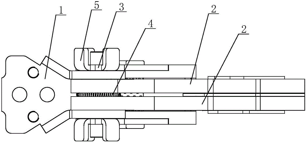
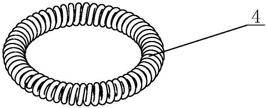
[0013] see Figure 1 to Figure 3 As shown, in this embodiment, a moving contact clamping structure of a circuit breaker includes a conductive bracket 1 and two pieces of moving contacts 2, and the two pieces of moving contacts 2 are mounted on the conductive bracket 1 through a rotating shaft 3, so that The rotating shaft 3 between the two moving contacts 2 is equipped with an elastic ring 4 that can deform along its radial direction. Limiting outer support 5.

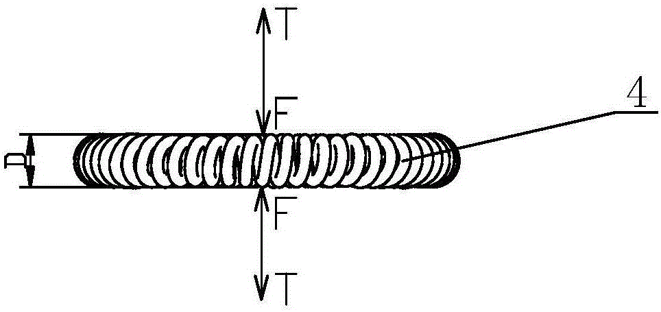
[0014] The elastic ring 4 is welded from the end to the end of the helical spring, and is in the shape of a ring as a whole. By compressing the radial dimension of the elastic ring 4, the outer diameter of the elastic ring 4 produces a recoverable elastic deformation within the elastic range, so that The elastic ring 4 generates an elastic...


PUM


Abstract

The invention discloses a moving contact clamping structure for a circuit breaker. The moving contact clamping structure comprises a conductive bracket and two moving contacts; the two moving contacts are mounted on the conductive bracket through a rotary shaft, wherein an elastic ring which can be deformable radially is mounted on the rotary shaft between the two moving contacts; a limiting part used for limiting the two moving contacts is mounted on the conductive bracket; and the outer side walls of the two moving contacts are in tight contact with the conductive bracket in a plane-to-plane manner through radial elastic force generated by the elastic ring. The moving contact clamping structure for the circuit breaker is simple in structure, low in cost, stable and reliable in clamping, capable of remarkably reducing dimensions of the elastic part under the premise of not reducing the clamping force of the moving contact structure, so as to reserve more space to enlarge sectional areas of conductive loops of the moving contacts and other parts, and capable of lowering internal resistance of the loop and laying foundation for improving the current level of a shell frame.

Description

technical field [0001] The invention relates to a circuit breaker, in particular to a clamping structure for a moving contact of the circuit breaker. Background technique [0002] In modern society, with the continuous advancement of science and technology, the continuous improvement of circuit breaker manufacturing technology, the continuous increase of grid capacity and the need for centralized power distribution, more and more circuit breakers are developing in the direction of miniaturization and high breaking. Miniaturization means developing a circuit breaker that can carry a larger current on the basis of the original smaller frame, and at the same time, the breaking index of the circuit breaker does not drop but rises. Under this strict design index, the traditional soft connection connection method is limited to a large movement space, which has a great hindering effect on the movement of the moving contact and affects the breaking time, which has been unable to mee...

Claims


Application Information

Patent Timeline
Patent Type & Authority Applications(China)
IPC IPC(8): H01H1/50
CPCH01H1/50
Inventor 时凯赵敏海杨杰
Owner WUXI XINHONGTAI ELECTRIC TECH CO LTD
Learn More