Main reflector interchange structure of satellite communication earth station antenna and technology for main reflector interchange structure

A main reflector and satellite communication technology, applied in the field of satellite communication, can solve the problems of unstable profile accuracy, waste of labor and time, low profile accuracy of the main reflector, etc., to improve profile accuracy, save costs and construction period Effect

Active Publication Date: 2017-05-10
盐城市星地通信设备有限公司
View PDF6 Cites 3 Cited by
  • Summary
  • Abstract
  • Description
  • Claims
  • Application Information

AI Technical Summary

Problems solved by technology

Not only the accuracy of the main reflector surface is not high, but also the overall repeated installation of the antenna head is unstable, labor and time are wasted in the installation process, and the maintenance cost of the antenna is also high, which is extremely unfavorable for the export market

Method used


Image

  • Main reflector interchange structure of satellite communication earth station antenna and technology for main reflector interchange structure
  • Main reflector interchange structure of satellite communication earth station antenna and technology for main reflector interchange structure
  • Main reflector interchange structure of satellite communication earth station antenna and technology for main reflector interchange structure

Examples


Embodiment 1

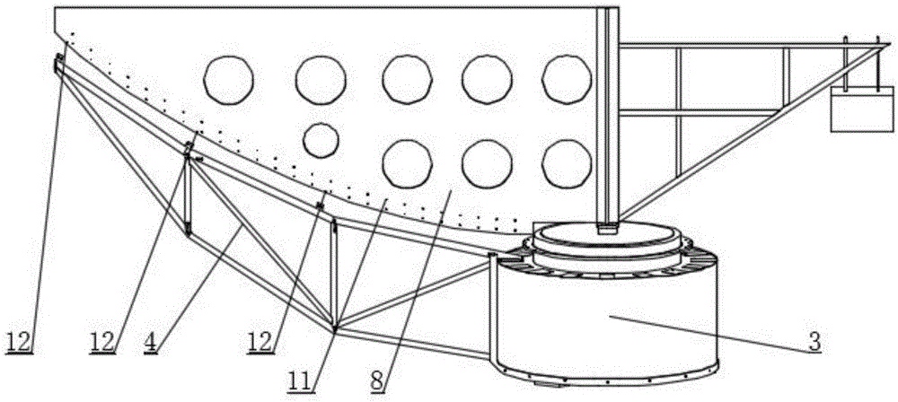
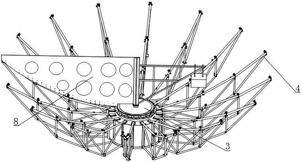
[0034] Embodiment 1: An interchange structure of the main reflecting surface of the antenna of the satellite communication earth station, such as figure 2 , image 3 , Figure 4 , Figure 5 , Figure 7 As shown, the antenna head assembly 1 is included. The antenna head assembly 1 includes a main reflective panel 2, a central body 3, a radiation beam 4, a truss rod 5, a connecting plate 6, and a mounting hole 7. A connecting plate 6 is installed at the joint of every two adjacent main reflecting panels 2 and on the radiation beam 4 to facilitate the connection and fixing of the radiation beam 4 and the main reflecting panel 2. The connecting plate 6 is provided with mounting holes 7 and cones Positioning pin holes 13, connecting plates 6 to connect the adjacent main reflecting panels 2 and radiation beams 4 by bolts; the radiation beams 4 are surrounded by truss rods 5, and the radiation beams 4 are connected by bolts and positioning taper pins Installed on the central body 3, t...

Embodiment 2

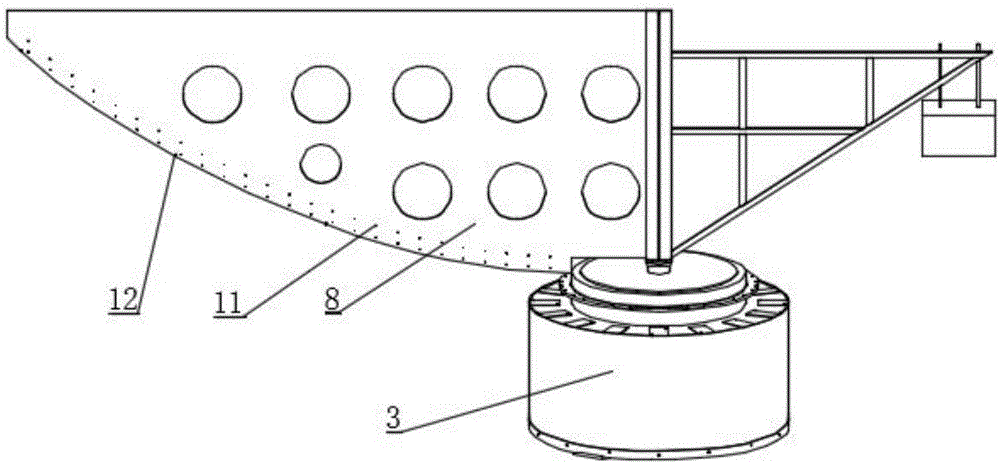
[0036] Embodiment 2: A detection device for detecting the installation and positioning of the interchange structure of the main reflection surface of the satellite communication earth station antenna, based on Embodiment 1, as figure 1 , Figure 5 , Image 6 Shown includes detection template 8, detection dial indicator 9, positioning bracket 10. The lower end of the detection template 8 is stuck at the inner stop of the upper end of the center body 3. The upper inner stop of the center body 3 and the upper surface of the center body 3 work together to test the template 8 Carrying out positioning detection template 8 The curve edge includes a number of frame support position detection points 12 and a number of main reflective panels 2 Curve detection point positioning holes 11, the detection template 8 and the curve are formed by CNC cutting to ensure that the main reflective panel 2 curve design As required, the reinforcement on the test sample 8 should be riveted to prevent weld...

Embodiment 3

[0037] Embodiment 3: An assembling process for the interchange structure of the main reflection surface of the satellite communication earth station antenna, based on the detection device of embodiment 2, includes the following steps:

[0038] Step one, such as figure 1 As shown, the detection template 8 is positioned based on the plane on the center body 3 and the inner stop;

[0039] Step two, such as figure 2 As shown, the radiating beam 4 is installed on the central body 3 to ensure that the central plane formed by the vertical lugs of the radiating beam 4 and the central axis of the central body 3 are on the same plane;

[0040] Step three, such as figure 2 As shown, the data of each supporting point of the main reflecting panel 2 of the radiation beam is detected according to the design requirements, the position error is adjusted, and the preliminary fix is ​​performed;

[0041] Step four, such as image 3 As shown, the data of the supporting points of all the radiation beams ...


PUM


Abstract

The invention discloses a main reflector interchange structure of a satellite communication earth station antenna and a technology for the main reflector interchange structure. The main reflector interchange structure comprises an overall antenna head, wherein the overall antenna head comprises main reflector panels, a center body, radiation beams, truss pull rods, connection plates and installation holes. According to the technical main points, the radiation beams are surrounded by the truss pull rods, are connected with and arranged on the center body through bolts and locating taper pins, are arranged at equal intervals and surround the center body for a circle; a center surface formed by various support lugs of the radiation beams and the center shaft of the center body are on the same surface; molded drilling is adopted by all installation holes in the main reflector panels, the center body and the radiation beams, so that the consistency of the installation holes and the precision of hole sites and hole diameters are ensured; the main reflector panels are formed by mold drawing and are assembled, riveted and molded by adopting a tooling clamp, the radiation beams are molded, processed and produced by adopting a setting mold, and the truss pull rods are processed and produced by adopting the setting mold, so that main reflector interchange is achieved through improvement of these processes.

Description

Technical field [0001] The invention relates to the technical field of satellite communication, in particular to an interchange structure of the main reflection surface of a satellite communication earth station antenna and its process. Background technique [0002] In the manufacturing process of satellite communication antenna manufacturers, the accuracy of the main reflecting surface of the antenna is regarded as the top priority of product quality. The accuracy of the main reflection surface of the split-lobe assembled satellite communication antenna is mainly guaranteed by the difference of the root mean square value of the measurement surface. The root mean square value difference of the single-lobe main reflector must be controlled to not less than 0.03mm, and the root mean square value difference of the final assembly must be controlled to not less than 0.05mm to ensure that the radio frequency index of the antenna meets the network access requirements of the satellite co...

Claims


Application Information

Patent Timeline
Patent Type & Authority Applications(China)
IPC IPC(8): H01Q15/14H01Q15/16G01B5/00
CPCG01B5/00G01B5/0002H01Q15/141H01Q15/165
Inventor 周建山张文桂
Owner 盐城市星地通信设备有限公司
Why Eureka
Try Eureka