A plug housing assembly and a sub-board plug

A technology of plug housing and components, which is applied in the direction of electrical components, parts of connecting devices, coupling devices, etc., can solve problems such as affecting the connection of connectors, easy tilting, unfavorable springback of elastic push rods, etc., so as to ensure the rebound performance , improve reliability, and eliminate the effect of asynchronous force

Active Publication Date: 2019-07-26
CHINA AVIATION OPTICAL-ELECTRICAL TECH CO LTD
View PDF6 Cites 0 Cited by
  • Summary
  • Abstract
  • Description
  • Claims
  • Application Information

AI Technical Summary

Problems solved by technology

[0005] However, when the floating shell of the sub-board plug and the shell of the plug part are relatively floating, the elastic push rod is always in a state of bending under force, and deformed under force for a long time, which is likely to cause elastic fatigue, which is not conducive to the rebound of the elastic push rod , especially when the external environment temperature has a large temperature difference change, the elastic push rod is easy to lose the resilience performance, so that the effective stop between the insulator and the floating shell cannot be guaranteed, resulting in the sub-board and the back board being mated in place At this time, the plug and socket may not be mated in place, seriously affecting the docking of the connector
In addition, the elastic push rod and the housing of the plug part are two parts. When the two parts are fixedly installed together, the consistency is poor, and the force of the two elastic push rods is not synchronized and uneven; and the two elastic The push rod is set on the same side of the plug part shell, so that the plug part shell is unevenly stressed, easy to tilt, and even causes the elastic push rod to fail before locking

Method used


Image

  • A plug housing assembly and a sub-board plug
  • A plug housing assembly and a sub-board plug
  • A plug housing assembly and a sub-board plug

Examples


Embodiment Construction

[0031] Embodiments of the present invention will be further described below in conjunction with the accompanying drawings.

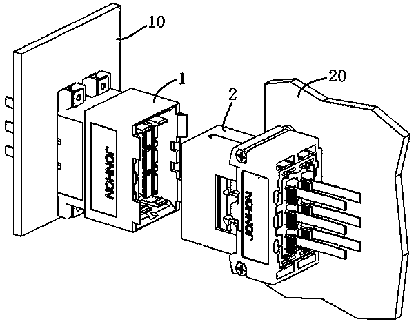
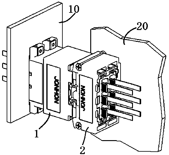
[0032]Specific embodiments of the plug connector of the present invention, such as figure 1 As shown, the daughter board plug of the present invention is installed on the daughter board 20 when in use, and is used for plugging and mating with the back board socket 1 installed on the back board 10 to realize optical signal transmission between the back board and the daughter board. Of course, in other implementation manners, the plug of the sub-board may also be a conductive plug, which is used to realize the transfer and transmission of electrical signals.

[0033] For the sake of clarity, the front and rear directions mentioned in the present invention refer to the insertion direction of the plug, and to be precise, the forward direction refers to the direction of the plug toward the socket.

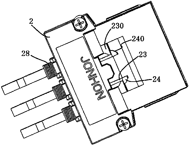
[0034] The daughterboard plug 2 of the present invention in...


PUM


Abstract

The invention discloses a plug shell assembly and a sub board plug. The plug shell assembly comprises a floating shell and an insulator mounted in the floating shell, wherein the insulator is provided with an elastic push rod; the elastic push rod comprises a rod body which extends from back to front in a suspension manner; a shell stop structure is arranged in the floating shell; a rod body stop structure, which is matched with the shell stop structure in a stopping manner and used for preventing the floating shell from moving forwards relative to the insulator, is arranged on the rod body; a plug contact part and a force-bearing part are arranged on the front side of the rod body stop structure on the rod body, wherein after the force-bearing part is inserted with a socket contact part in a proper position, the force-bearing part is jacked by a socket shell to enable the elastic push rod to be elastically deformed so as to remove a stop matching relation between the elastic push rod and the floating shell; and an accommodating space which is used for allowing the elastic push rod to elastically recover is also formed in the floating shell after the elastic push rod floats forwardly relative to the plug insulator when the stop matching relation between the elastic push rod and the floating shell is removed. The elastic push rod of the sub board plug is high in rebound elasticity, and stable and reliable in use.

Description

technical field [0001] The invention relates to a plug shell assembly and a sub-board plug using the plug shell assembly. Background technique [0002] The circuit printed board is an important electronic component in the communication equipment cabinet, which is divided into a vertically placed backplane and a horizontally placed subboard. During the operation of the device, the communication data needs to be transmitted between the backplane and the daughter board. In the traditional way, most optical jumpers are used to realize the intermediate transfer between the backplane and the sub-board, but a large number of optical jumpers occupy space, the wiring is messy, and the later maintenance is very inconvenient. In response to such problems, the inter-board optical fiber connector came into being. Through the inter-board optical fiber connector, the optical fiber jumper-free connection between the printed board and the printed board can be realized, and it can be directl...

Claims


Application Information

Patent Timeline
Patent Type & Authority Patents(China)
IPC IPC(8): H01R13/631H01R13/629H01R13/502
CPCH01R13/502H01R13/629H01R13/6315
Inventor 周生贺余永强徐耕
Owner CHINA AVIATION OPTICAL-ELECTRICAL TECH CO LTD
Why Eureka
Try Eureka