Magnetic suspension flywheel battery for sandwich-type electric car and work method thereof

A technology for electric vehicles and flywheel batteries, which is applied to electric vehicles, electric components, holding devices using magnetic attraction or thrust, etc., can solve the problems of large standby loss, large vibration noise, and large motor volume of flywheel batteries, and achieves suppression of gyroscopes. effect, no-load loss reduction, efficiency improvement effect

Active Publication Date: 2017-05-10
JIANGSU UNIV
View PDF3 Cites 26 Cited by
  • Summary
  • Abstract
  • Description
  • Claims
  • Application Information

AI Technical Summary

Problems solved by technology

In addition, the motors used in the flywheel batteries of the prior art mostly adopt the traditional radial air gap structure. At the same time, in order to reduce the reluctance of the magnetic circuit, silicon steel sheets with high magnetic permeability are laminated to make the iron core, and the existence of the iron core It also leads to problems such as large volume, heavy weight, large loss, and large vibration and noise of the motor, which in turn leads to large standby loss of the flywheel battery

Method used


Image

  • Magnetic suspension flywheel battery for sandwich-type electric car and work method thereof
  • Magnetic suspension flywheel battery for sandwich-type electric car and work method thereof
  • Magnetic suspension flywheel battery for sandwich-type electric car and work method thereof

Examples


Embodiment Construction

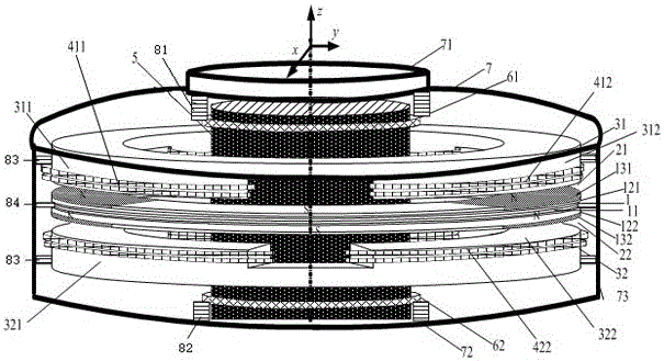
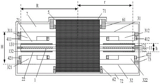
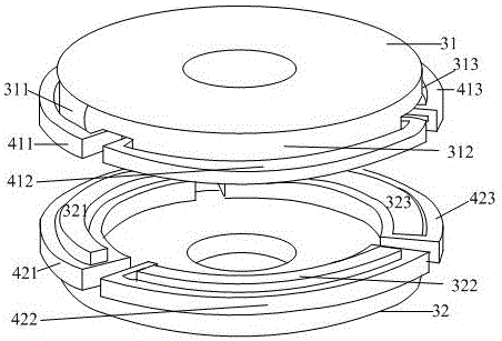
[0024] like figure 1 and figure 2 As shown, the magnetic levitation flywheel battery for sandwich type electric vehicles of the present invention has a vacuum chamber 7, and the vacuum chamber 7 is a vacuum chamber surrounded by a top end cover 71, a bottom end cover 72 and a drum 73, wherein the top of the drum 73 The center and the bottom center are respectively openings, the top central opening is sealed and fixed with a top end cover 71, and the bottom central opening is sealed and fixed with a bottom end cover 72. Inside the vacuum chamber 7, a disc-type flywheel motor 1, a vertical rotating shaft 5, and two identical disc-shaped magnetic bearings 31, 32 are arranged.

[0025] The center of the inside of the vacuum chamber 7 is a vertical shaft 5, the central axis of the vertical shaft 5 coincides with the central axis of the vacuum chamber 7, and the top of the vertical shaft 5 is coaxial with an upper protective bearing 61, and the upper protective bearing 61 is at th...


PUM


Abstract

The present invention discloses a magnetic suspension flywheel battery for a sandwich-type electric car and a work method thereof. A vertical rotation shaft is arranged at the center of the internal portion of a vacuum chamber, a disc-type flywheel motor is coaxially arranged at the center of the axial direction of the vertical rotation shaft, disc-type magnetic bearings having the same structure, being arranged at the axial direction in the longitudinal symmetry mode relative to the disc-type flywheel motor and being sleeved at the outer portion of the vertical rotation shaft are coaxially arranged at the upper portion and the lower portion of the disc-type flywheel motor, and each disc-type magnetic bearing is wound with a set of radial control coils; the disc-type flywheel motor is composed of a stator, two rotors and two sets of permanent magnets, the stator is located at the center of the disc-type flywheel motor and coaxially arranged at the outer portion of the vertical rotation shaft, and the two rotors are respectively and symmetrically arranged at upper and lower sides of the stator and coaxially and fixedly sleeved on the vertical rotation shaft; and the two sets of the permanent magnets are respectively pasted on the surfaces, back to the stator, of the two rotors along the peripheral directions, the whole structure of the flywheel battery is a disc-type structure, the disc-type magnetic bearings and the disc-type flywheel motor are both the flat structures to inhibit the gyroscopic effect of the rotors.

Description

technical field [0001] The invention relates to the field of flywheel batteries (also called flywheel energy storage devices), in particular to a magnetic levitation flywheel battery for electric vehicles. Background technique [0002] The maglev flywheel battery is a high-efficiency, clean, mobile secondary discharge device that stores mechanical energy instead of storing electrical energy. It uses a non-contact rotating flywheel to store energy. It has the advantages of high specific power and specific energy, fast charging, high speed, long life and environmental friendliness. It is widely used in transportation, aerospace, electric energy and other fields. [0003] The working principle of the maglev flywheel battery is: the maglev flywheel battery uses the power electronic conversion device to input electric energy from the outside to drive the motor to rotate, the motor drives the flywheel rotor to rotate, and the flywheel stores kinetic energy (mechanical energy). Whe...

Claims


Application Information

Patent Timeline
Patent Type & Authority Applications(China)
IPC IPC(8): H02K7/02H02N15/00
CPCH02K7/025H02N15/00Y02E60/16Y02T10/64
Inventor 张维煜朱熀秋陈涛杨恒坤
Owner JIANGSU UNIV
Why Eureka
Try Eureka