Flywheel energy storage device based on outer rotor bearingless permanent magnet synchronous motor

A permanent magnet synchronous motor, flywheel energy storage technology, applied to synchronous motors, synchronous machines, electromechanical devices with static armatures and rotating magnets, etc., can solve the problems of low control difficulty, achieve good heat dissipation performance and compact structure , The effect of reducing the difficulty and cost of axial suspension

Active Publication Date: 2021-06-25
JIANGSU UNIV
View PDF16 Cites 1 Cited by
  • Summary
  • Abstract
  • Description
  • Claims
  • Application Information

AI Technical Summary

Problems solved by technology

[0005] The purpose of the present invention is to solve the problems existing in the existing flywheel energy storage device, and propose a flywheel energy storage device based on the outer rotor bearingless permanent magnet synchronous motor with large capacity and low loss, which has higher flywheel speed and system reliability sex, less difficult to control

Method used


Image

  • Flywheel energy storage device based on outer rotor bearingless permanent magnet synchronous motor
  • Flywheel energy storage device based on outer rotor bearingless permanent magnet synchronous motor
  • Flywheel energy storage device based on outer rotor bearingless permanent magnet synchronous motor

Examples


Embodiment Construction

[0020] The following is a further detailed description of the preferred embodiments of the present invention, which are only used to explain the present invention, but should not be construed as limiting the present invention.

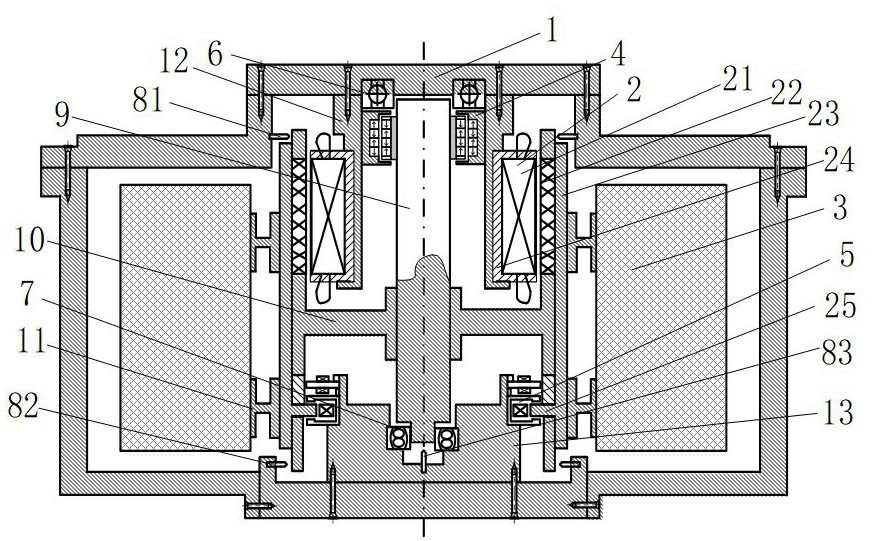
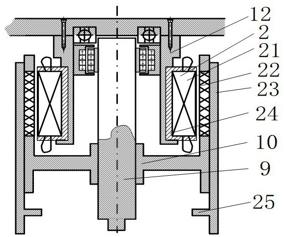
[0021] Such as figure 1 As shown, the exterior of a flywheel energy storage device based on an outer rotor bearingless permanent magnet synchronous motor of the present invention is a vacuum-tight casing 1, the upper part of the vacuum-tight casing 1 is an upper end cover, the lower part is a lower end cover, the upper end cover and the lower end The covers are sealed and fixedly connected to the housing. Inside the vacuum-tight casing 1, there are statorless coreless bearingless permanent magnet synchronous motor 2, flywheel rotor 3, axial passive magnetic bearing 4, three-degree-of-freedom radial-axial hybrid magnetic bearing 5, auxiliary bearing 6, self-aligning Ball bearing 7, rotating shaft 9, inner wheel hub 10, outer wheel hub 11, upper cylindr...


PUM


Abstract

The invention discloses a flywheel energy storage device based on an outer rotor bearingless permanent magnet synchronous motor. A rotating shaft is arranged at the center of the interior of a vacuum closed casing; the upper end of the rotating shaft is connected with an upper cylindrical table through an axial passive magnetic bearing; the upper cylindrical table is fixedly sleeved with a stator bearingless permanent magnet synchronous motor; a motor inner stator coaxially and fixedly sleeves the upper cylindrical table; the inner wall of the middle section of a motor outer rotor is fixedly connected to the rotating shaft through an inner hub; the outer wall of the motor outer rotor is fixedly connected to the inner wall of a the flywheel rotor through an outer hub; the lower end of the rotating shaft is connected to the center of the lower cylindrical table through a self-aligning ball bearing; a three-degree-of-freedom radial-axial hybrid magnetic bearing is arranged between the upper end of the cylindrical table and the motor outer rotor; the lower end of the motor outer rotor extends downwards in the axial direction; a circular truncated cone horizontally extends inwards in the radial direction on the inner wall of the lower section of the motor outer rotor; and the circular truncated cone serves as a magnetic bearing outer rotor of the three-degree-of-freedom radial-axial hybrid magnetic bearing. According to the flywheel energy storage device based on the outer rotor bearingless permanent magnet synchronous motor of the invention, higher energy can be obtained, and a large-capacity requirement is realized.

Description

technical field [0001] The invention belongs to a flywheel energy storage device capable of converting electric energy into flywheel kinetic energy, and is applicable to the fields of satellite energy storage batteries, power peak regulation, communication, electric vehicles, etc., and can release kinetic energy into electric energy when needed. Background technique [0002] With the increasing demand of users for power, the contradiction between power supply and demand has become increasingly prominent. For example, the installed capacity of the system is difficult to meet the peak load requirements, and users have higher and higher requirements for power quality and power supply reliability, especially in recent years. With the rapid development of renewable energy technology, its intermittence and randomness have a great impact on the power grid, and energy storage technology can provide a simple and effective solution. Various forms of energy storage devices can obtain e...

Claims


Application Information

Patent Timeline
Patent Type & Authority Applications(China)
IPC IPC(8): H02K7/02H02K11/21H02K7/09H02K7/08H02K5/04H02K21/22
CPCH02K7/025H02K11/21H02K7/09H02K7/085H02K5/04H02K21/222Y02E70/30
Inventor 朱熀秋还浚萁
Owner JIANGSU UNIV
Why Eureka
Try Eureka