A synchronous thruster device

A technology of a propeller with the same structure, applied in the field of synchronous propeller devices, can solve the problems of high requirements on the waterproof performance of the bottom of the ship, complex structure of the propeller, difficult maintenance, etc., and achieve a strong gyroscopic effect, simple structure and low operating cost. Effect

Inactive Publication Date: 2015-07-29
李敏华
View PDF7 Cites 0 Cited by
  • Summary
  • Abstract
  • Description
  • Claims
  • Application Information

AI Technical Summary

Problems solved by technology

However, the structure of the propeller is complicated, the number of movable fins is large, and maintenance is difficult. At the same time, the waterproof performance of the bottom of the ship is high.

Method used


Image

  • A synchronous thruster device
  • A synchronous thruster device
  • A synchronous thruster device

Examples


Embodiment 1

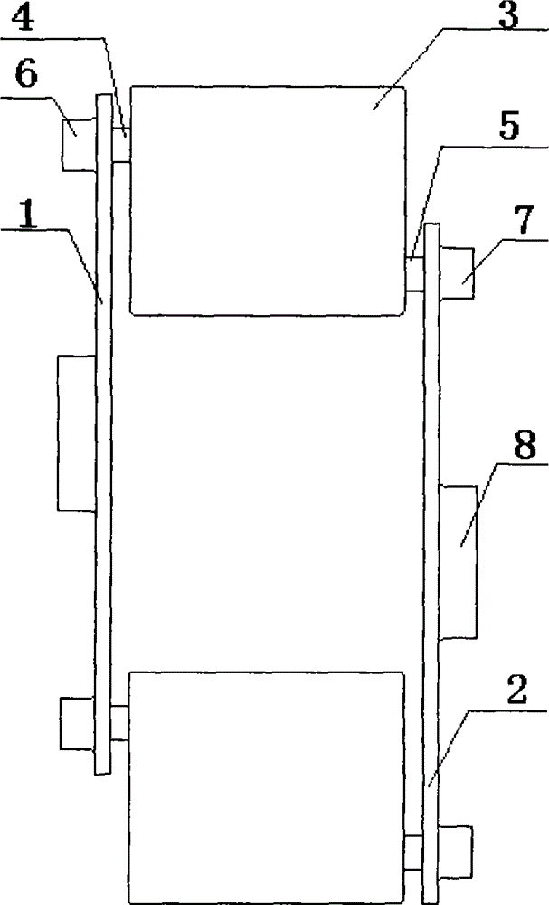
[0033] as attached figure 1 In the synchronous propeller device with two wheels and two fins shown, the upper end of the web plate 3 is connected to the upper rotating shaft 4 by clamping and welding, and the upper rotating shaft 4 is connected to the upper runner 1 by inserting the upper shaft seat 6; the web plate 3. The lower end and the lower rotating shaft 5 are also connected by clamping and welding. The lower rotating shaft 5 is connected to the lower runner 2 by inserting the lower shaft seat 7; the web plate 3 is perpendicular or parallel to the rotating shaft 8 of the runner; the upper shaft Rolling bearings are housed in the seat 6 and the lower shaft seat 7. The two rectangular fins 3 are installed symmetrically, and the connection mode is the same, and the rotating shaft 8 is connected to the power unit. The runner is made of steel plate into a square shape and fastened by flanges. The diameter of the runner is 5m, the structure of the two webs is the same, the ...

Embodiment 2

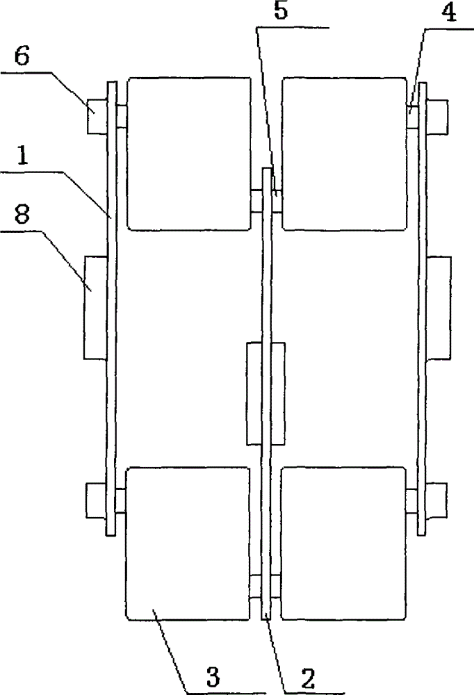
[0035] as attached figure 2 In the synchronous propeller device with two wheels and four fins shown, the upper end of the web plate 3 is connected with the upper rotating shaft 4 by clamping and welding, and the upper rotating shaft 4 is connected with the upper runner 1 by inserting the upper shaft seat 6; the web plate 3. The lower end and the lower rotating shaft 5 are also connected by clamping and welding. The lower rotating shaft 5 is connected to the lower runner 2 by inserting the lower shaft seat 7; the web plate 3 is perpendicular or parallel to the rotating shaft 8 of the runner; the upper shaft Sliding bearings are housed in the seat 6 and the lower shaft seat 7, and four web plates 3 are installed symmetrically to keep the structure of dynamic balance. The rotating shaft 8 is connected with the power unit. The runners are diamond-shaped, manufactured from steel plates and fastened by flanges.

[0036] The device is installed in the cabin of the catamaran in the...

Embodiment 3

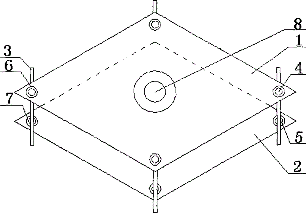
[0038] as attached image 3The semi-submerged synchronous propeller with three wheels and four fins shown has two upper runners 1 and one lower runner 2 as the propeller of this structure. The upper end of the web plate 3 is connected to the upper rotating shaft 4 by clamping and welding, and the upper rotating shaft 4 is connected to the upper runner 1 by inserting the upper shaft seat 6; the lower end of the web plate 3 and the lower rotating shaft 5 are also connected by clamping and welding Connected in a manner, the lower rotating shaft 5 is inserted into the lower shaft seat 7 and connected with the lower runner 2, the web plate 3 is perpendicular or parallel to the rotating shaft 8 of the runner, and rolling bearings or sliding bearings are housed in the upper shaft seat 6 and the lower shaft seat 7. The four fins 3 are installed symmetrically, and the installation methods are all the same, and the rotating shaft 8 is connected to the power unit. The runner is made of ...


PUM


Abstract

The invention discloses a synchronizing propeller device. The synchronizing propeller device mainly comprises paddle blades (3) and rotating wheels, wherein an upper rotating shaft (4) of the paddle blades (3) is connected with an upper rotating wheel by being inserted into an upper shaft seat (6), a lower rotating shaft (5) of the paddle blades (3) is connected with a lower rotating wheel by being inserted into a lower shaft seat (7), the paddle blades (3) are perpendicular or parallel to a rotating shaft (8) of the rotating wheels, the a rotating shaft (8) is directly connected with an output shaft of a power device, and each paddle blade (3) is symmetrically mounted. In a rotation process, the paddle blades (3) always perpendicularly enter into water. The device is widely used, and can be used in the aspects of ship propellers, water turbines, steam turbines, hydroelectric generation or tidal power generation and the like, the ship with the propeller provided by the invention can sail in shoal water, and also can sail in a water plant zone, a trash floating zone and a subaquatic sludge zone, so that the ship with the propeller has wide sailing are; and the synchronizing propeller device is low in manufacturing cost and simple and convenient to maintain.

Description

technical field [0001] The invention relates to the field of thrusters, in particular to a synchronous thruster device. Background technique [0002] The most advanced paddle wheel is a paddle wheel with variable web entry angle invented by the British. This "paddle wheel" propeller is a propeller commonly used in ships in the early days, and is suitable for ships navigating on inland rivers and lakes. The entire propeller is in the shape of a wheel, and the wheel shaft is placed horizontally along the width of the ship and above the waterline of the ship. There are fins on the periphery of the wheel, but the structure of this invention is asymmetrical, and the rotation of each corresponding mass point during rotation The penetration is not equal, so the speed is very low, resulting in low efficiency and large diameter, and the draft of the web cannot exceed half the radius of the paddle wheel; otherwise, when the paddle wheel rotates, the lifting force of the ship will be i...

Claims


Application Information

Patent Timeline
Patent Type & Authority Patents(China)
IPC IPC(8): B63H1/30
Inventor 李敏华李岩松
Owner 李敏华
Why Eureka
Try Eureka