Semi-submerged propeller

A thruster and semi-submerged technology, which is applied in the direction of non-rotating propulsion elements, etc., can solve the problems of small draft hydraulic area of ​​the web, insufficient balance of web force, poor stability, etc., and achieve a balanced distribution of force , dynamic balance, and simple structure

Inactive Publication Date: 2012-09-12
李敏华
View PDF7 Cites 4 Cited by
  • Summary
  • Abstract
  • Description
  • Claims
  • Application Information

AI Technical Summary

Problems solved by technology

Installing it on a ship can make the ship sail in shallow water areas, and also in water plants, floating garbage areas, and semi-water mud areas. Not good, because the force on the fins is not balanced enough, the draft of the fins and the hydraulic area generated are small, and the driving force generated is small, so the speed of the boat is not fast

Method used


Image

  • Semi-submerged propeller
  • Semi-submerged propeller
  • Semi-submerged propeller

Examples


Embodiment 1

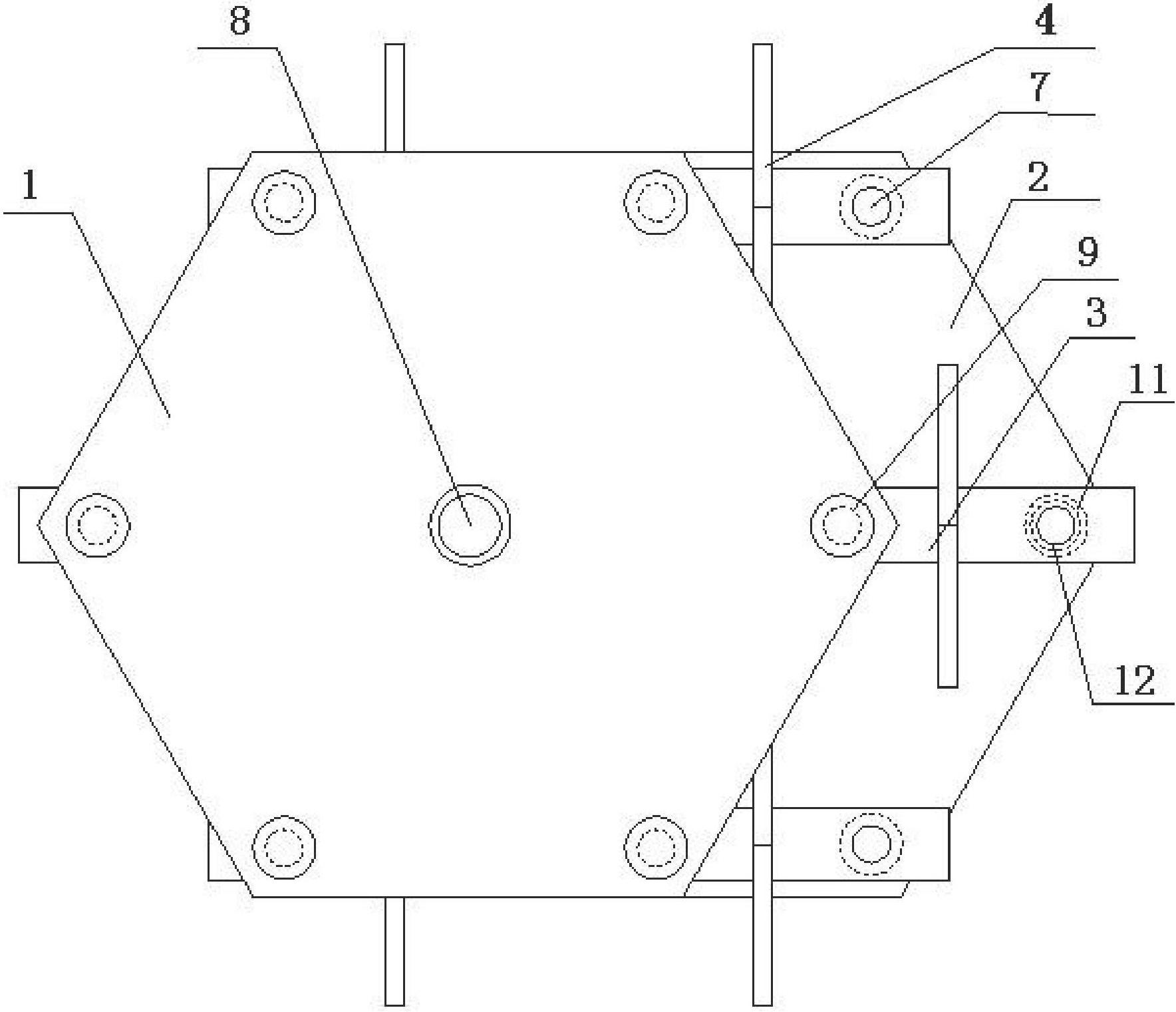
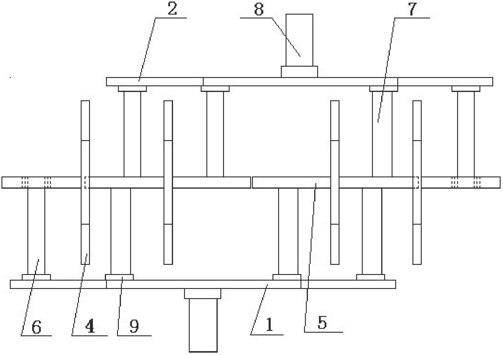
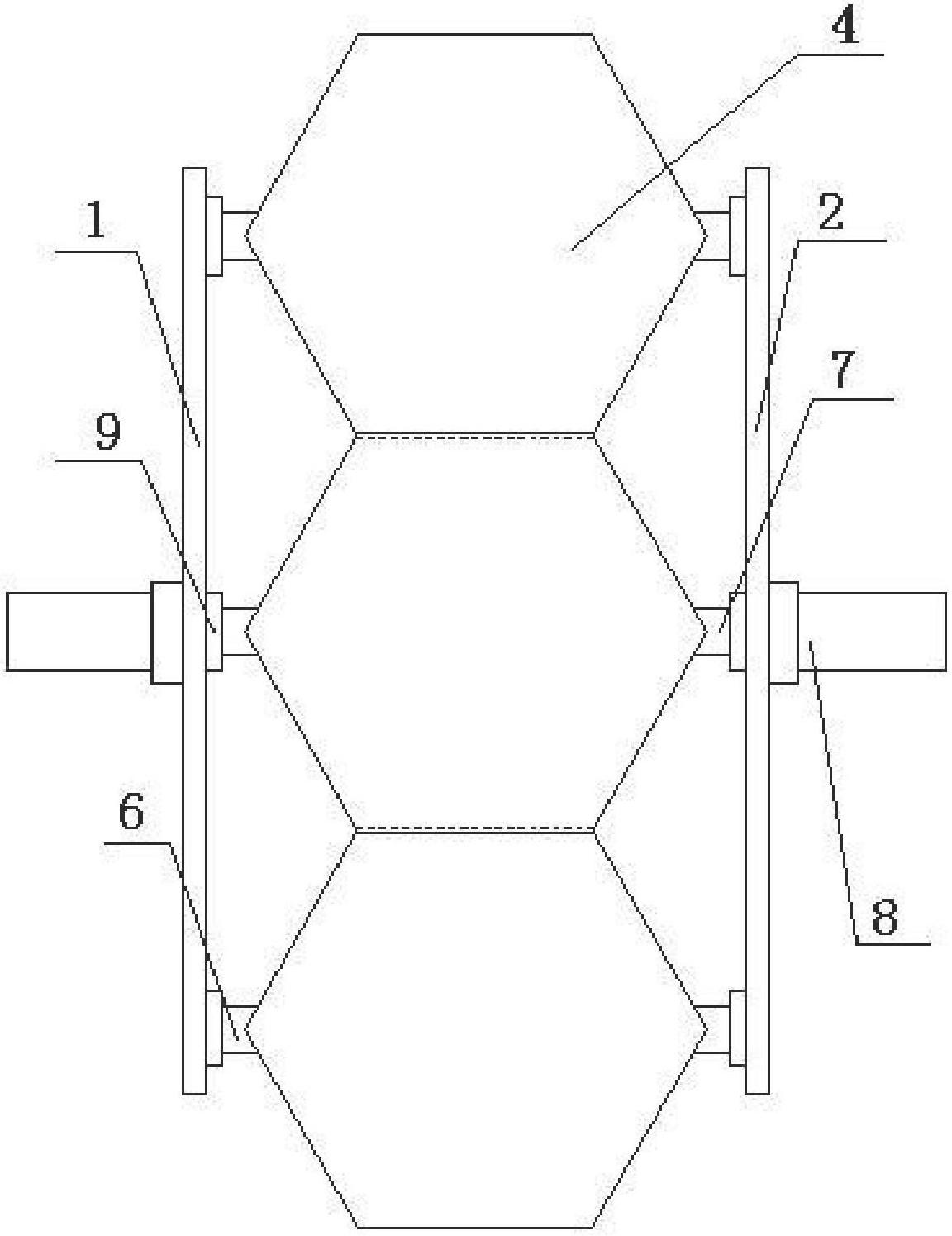
[0060] Such as figure 1 , figure 2 , image 3 with Figure 4 The semi-submerged propeller shown includes the runner a1 and the runner b2 whose axial center position of the central rotating shaft 8 is relatively staggered, and six sets of fin assembly 3 that are evenly distributed relative to the runner a1 and runner b2; The assembly 3 is composed of a web plate 4, a connecting rod 5 formed by a beam and two bearing installation holes 10 opened on the connecting rod 5. The web plate 4 is vertically installed in the middle of the connecting rod 5. The plane where the web plate 4 is located is in line with the The horizontal plane is vertical; a bearing seat 11 is installed in the bearing installation hole 10, and a bearing 12 is installed in the bearing seat 11, and the bearing 12 adopts a sliding bearing; the runner a1 is provided with a web shaft a6, and the runner a1 is embedded through the web shaft a6 The bearing 12 is connected with the web assembly 3; the web shaft b7...

Embodiment 2

[0065] Such as Figure 5 , Image 6 with Figure 7 The semi-submerged propeller shown includes the runner a1 and the runner b2 whose axial center position of the central rotating shaft 8 is relatively staggered, and four sets of flipper assemblies 3 that are evenly distributed relative to the runner a1 and the runner b2; the flippers The assembly 3 is composed of two webs 4, a connecting rod 5 composed of a beam, and two bearing installation holes 10 opened on the connecting rod 5. The webs 4 are vertically and symmetrically installed on both sides of the connecting rod 5, forming an I-shaped structure. The plane where the web plate 4 is located is perpendicular to the horizontal plane; a bearing seat 11 is installed in the bearing mounting hole 10, and a bearing 12 is installed in the bearing seat 11, and a sliding bearing is used; the web plate rotating shaft a6 is arranged on the runner a1, and the runner a1 passes through The plate shaft a6 is embedded in the bearing 12 ...

Embodiment 3

[0069] Such as Figure 8 with Figure 9 The semi-submerged propeller shown includes the runner a1 and the runner b2 whose axial positions of the central rotating shaft 8 are relatively staggered, and two sets of fin assembly 3 that are evenly distributed relative to the runner a1 and runner b2; The assembly 3 is composed of two webs 4, a connecting rod 5 composed of a beam, and two bearing installation holes 10 opened on the connecting rod 5. The webs 4 are vertically and symmetrically installed on both sides of the connecting rod 5, forming an I-shaped structure. The plane where the webbed plate 4 is located is perpendicular to the horizontal plane; a bearing seat 11 is installed in the bearing mounting hole 10, and a bearing 12 is installed in the bearing seat 11, and a rolling bearing is used; the webbed shaft a6 is arranged on the runner a1, and the runner a1 passes through The plate shaft a6 is embedded in the bearing 12 and connected with the web assembly 3; the web sha...


PUM


Abstract

The invention discloses a semi-submerged propeller. The semi-submerged propeller comprises a runner a (1) and a runner b (2), as well as more than two groups of paddle board assemblies (3) which are uniformly distributed relative to the runner a (1) and the runner b (2), wherein the positions of axle centers of central rotating shafts (8) of the runner a (1) and the runner b (2) are staggered relatively; the runner a (1) is embedded in a bearing (12) through a paddle board rotating shaft a (6) and connected with the paddle board assemblies (3); and the runner b (2) is embedded into the other bearing (12) through a paddle board rotating shaft b (7) and connected with the paddle board assemblies (3), the central rotating shafts (8) are arranged at the centers of the runner a (1) and the runner b (2), and the central rotating shafts (8) are connected with a power output device or input device. The semi-submerged propeller disclosed by the invention can be mounted on a ship, paddle boards can always vertically enter water, the energy of the water can be fully utilized, and the speed of the ship becomes faster; and the semi-submerged propeller has the advantages of good stability, low cost and convenience in maintenance, and can be simultaneously used as a power device to be further expanded to the fields of hydraulic turbines, low-water hydraulic power generation, tidal power generation, ocean current or sea current power generation and the like.

Description

technical field [0001] The invention relates to the field of thrusters, in particular to a semi-submerged thruster capable of increasing the hydraulic area. Background technique [0002] At present, the propellers commonly used in ships and warships are water jet propellers or propeller propellers. The propeller propeller rotates after being powered by the ship's power plant, pushes the water to the back of the ship, and uses the reaction force of the water to push the ship forward. The propeller is simple in structure, light in weight and high in efficiency, and is protected only when it is installed below the waterline. If propeller propellers are used in shallow water ships, it is difficult for the ship to navigate in water plants, floating garbage areas, and semi-water sludge areas, because it is easy to cause water plants, garbage, etc. to attach to the propeller or damage the propeller, so that the propeller cannot operate normally; In the lower shallow water area, t...

Claims


Application Information

Patent Timeline
Patent Type & Authority Applications(China)
IPC IPC(8): B63H1/30
Inventor 李敏华李岩松
Owner 李敏华
Why Eureka
Try Eureka