LCC resonant converter PWM phase shift mixed control and efficiency optimization method

A resonant converter, efficiency optimization technology, applied in the direction of converting DC power input to DC power output, control/regulation systems, instruments, etc., can solve problems such as reducing the efficiency of resonant converters, reducing converter efficiency, and large device stress. To achieve the effect of enhanced degree of control freedom, improved degree of freedom, and small resonant current

Active Publication Date: 2017-05-10
SOUTHEAST UNIV
View PDF5 Cites 11 Cited by
  • Summary
  • Abstract
  • Description
  • Claims
  • Application Information

AI Technical Summary

Problems solved by technology

If the switching frequency continues to increase, the power factor of the resonant tank will decrease, which will lead to an increase in commutation and reduce the efficiency of the resonant converter.
In other words, traditional phase-shift control cannot achieve a wide range of soft switching
[0006] The increase of converter resonant current will bring more conduction loss and greater device stress, resulting in lower converter efficiency
Under traditional phase-shift control, reducing the resonant current and ensuring the realization of ZVS are a pair of contradictions, that is, optimizing the conduction loss and switching loss cannot be realized at the same time, and optimizing one of them will inevitably destroy the characteristics of the other.

Method used


Image

  • LCC resonant converter PWM phase shift mixed control and efficiency optimization method
  • LCC resonant converter PWM phase shift mixed control and efficiency optimization method
  • LCC resonant converter PWM phase shift mixed control and efficiency optimization method

Examples


Embodiment Construction

[0052] The present invention will be further described below in conjunction with the accompanying drawings.

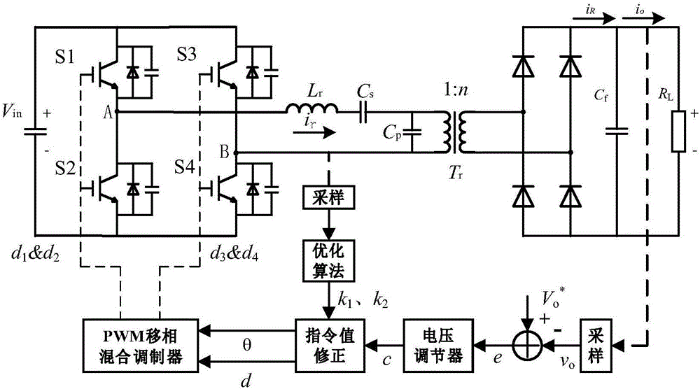
[0053] The present invention proposes a PWM phase-shifting hybrid control and efficiency optimization method for LCC resonant converter, the block diagram of the control system is as follows image 3 shown. The main steps include:

[0054] (1) Sample the output voltage of the LCC resonant converter, make a difference with the reference value and use it as the input of the voltage regulator to obtain the output c;

[0055] (2) Sampling the resonant current of the LCC resonant converter, and obtaining two correction coefficients k through the optimization algorithm 1 、k 2 ;

[0056] (3) use k 1 、k 2 Calculate and correct the output command value c of the voltage regulator to obtain two command values ​​of the PWM phase shift hybrid control method: phase shift angle θ and duty cycle d;

[0057] (4) Input the command value of the phase shift angle θ and the duty cyc...


PUM


Abstract

The invention discloses an LCC resonant converter PWM phase shift mixed control and efficiency optimization method. The method comprises the following steps: carrying out sampling on output voltage of a converter, obtaining voltage difference between an output voltage sample value and a reference value and serving the voltage difference as the input of a voltage regulator, and obtaining an output value c; carrying out sampling on resonance current of the converter, and carrying out optimization algorithm to obtain two coefficients k1 and k2; carrying out calculation and correction on the output instruction value c of the voltage regulator through the coefficients k1 and k2 to obtain two instruction values, that is, phase shifting angle theta and duty ratio d, of the PWM phase shift mixed control method; and inputting the phase shifting angle and the duty ratio instruction values to a PWM phase shift mixed modulator to obtain driving signals of four switching tubes at a primary side of the resonant converter. The method improves control freedom degree of the converter; and under the condition of maintaining specific output power invariant and ensuring ZVS realization, the resonance current is allowed to be minimum by adjusting the coefficients and changing combination of control variables, and efficiency of the converter is improved.

Description

technical field [0001] The invention relates to the technical field of power electronics, in particular to a PWM phase-shift hybrid control and efficiency optimization method for an LCC resonant converter. Background technique [0002] High frequency is one of the development trends of modern power electronics technology. Realizing high frequency can increase the power density of the system and reduce the weight and volume of the device. Traditional PWM switching converters work in the hard switching state of forced on and off. Due to the non-ideal characteristics of power electronic switching devices, they are usually turned on when the voltage is not zero or turned off when the current is not zero. This results in a large switching loss and high heat generation of the switching device. Since the switching loss is proportional to the switching frequency, when the switching frequency increases, the switching loss and heat generation of the switching device will also increas...

Claims


Application Information

Patent Timeline
Patent Type & Authority Applications(China)
IPC IPC(8): H02M3/335
CPCH02M3/3353H02M1/0025Y02B70/10Y02P80/10
Inventor 赵剑锋仲宙宇高铁峰张云龙
Owner SOUTHEAST UNIV
Why Eureka
Try Eureka