
Design method and circuit of a dual-band non-uniform transmission line impedance converter

A technology of impedance converter and design method, applied in the direction of impedance network, electrical components, multi-terminal pair network, etc., can solve the problems of large physical size, parasitic passband, large insertion loss, etc., and achieve small reflection coefficient, small physical size, Bandwidth effect

Active Publication Date: 2020-11-06
汪茂稳
View PDF9 Cites 0 Cited by
  • Summary
  • Abstract
  • Description
  • Claims
  • Application Information

AI Technical Summary

Problems solved by technology

However, dual-band impedance transformers based on uniform transmission lines often have defects such as parasitic passbands, large insertion loss, narrow bandwidth, and large physical size, which greatly restricts their applications.

Method used


Image

  • Design method and circuit of a dual-band non-uniform transmission line impedance converter
  • Design method and circuit of a dual-band non-uniform transmission line impedance converter
  • Design method and circuit of a dual-band non-uniform transmission line impedance converter

Examples


Embodiment Construction

[0034] The following will clearly and completely describe the technical solutions in the embodiments of the present invention with reference to the drawings in the embodiments of the present invention. The following are only preferred embodiments and do not constitute a limitation to the protection scope of the present invention.

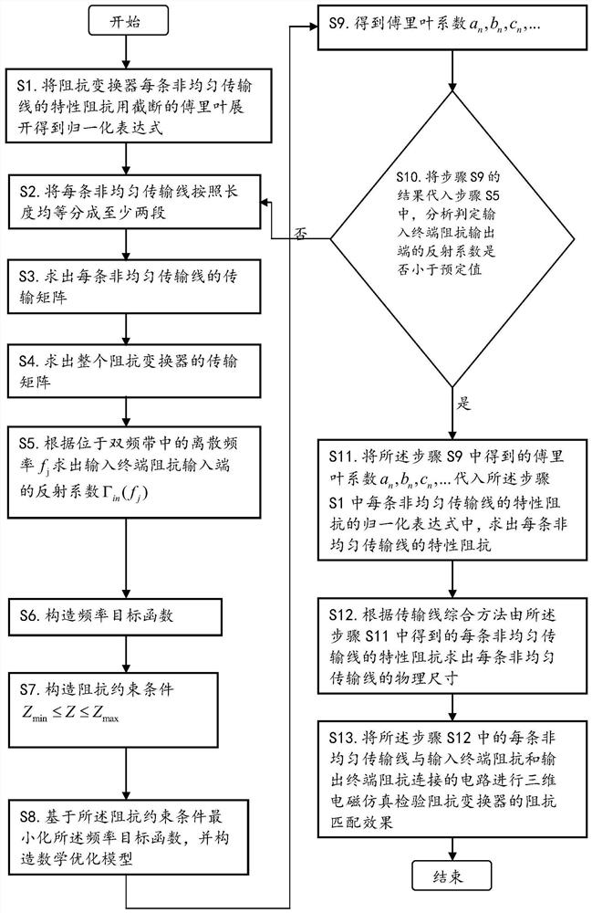
[0035] see figure 1 , is a flowchart of a design method for a dual-band non-uniform transmission line impedance transformer provided by the present invention. In this embodiment, the design method of a dual-band non-uniform transmission line impedance converter includes the following steps:

[0036] S1. Expand the characteristic impedance of each non-uniform transmission line of the impedance transformer with a truncated Fourier and obtain a normalized expression

[0037]

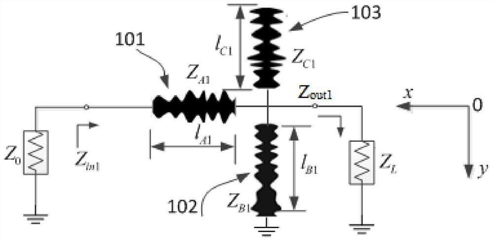
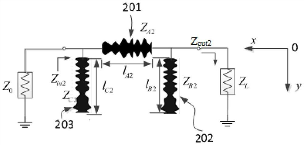
[0038] Among them, i is the distinguishing subscript of different circuits, A~E is the distinguishing subscript of each non-uniform transmission line in a circuit, Z 0 is t...


PUM


Abstract

A circuit and a design method for a dual-band non-uniform transmission line impedance converter. The method optimizes the structural size of an impedance converter by means of a mathematical optimization model, changes the corresponding transmission line of the impedance converter into a non-uniform transmission line, and causes the width of the transmission line to continuously change in a longitudinal direction, thereby realizing a smooth transmission of electromagnetic wave signals on the transmission line. The circuit comprises a T-type impedance converter, an n-type impedance converter and an H-type impedance converter. The impedance converter implemented by means of the design method has a small reflection coefficient, large harmonic suppression, small insertion loss, a large bandwidth, a physical size smaller than that of a conventional uniform transmission line impedance converter, and a more flexible design. Moreover, the impedance converter can be used for matching any plural number of terminal impedances without any centralized reactance element, and consumes few resources and is widely applicable.

Description

technical field [0001] The invention relates to the field of communication technology, in particular to a design method and circuit of a dual-band non-uniform transmission line impedance converter. Background technique [0002] Microwave technology is widely used in industry, agriculture, remote sensing, military and other industries. In order to meet the development requirements of civil communications, electronic detectives and electronic countermeasures, microwave communication systems are developing in the direction of high performance, miniaturization, broadband and multi-band. As a waveguide system for transmitting electromagnetic waves, the microwave transmission line has always been the most basic and important part of all microwave components. However, most of the current research focuses on the direction of the uniform transmission line, mainly because the characteristic parameters of the uniform transmission line can be determined by the corresponding These parame...

Claims


Application Information

Patent Timeline
Patent Type & Authority Patents(China)
IPC IPC(8): H03H7/38
CPCH03H7/38
Inventor 汪茂稳闵国新周新辉徐铭罗中良
Owner 汪茂稳
Learn More