Joining method of amorphous alloy electronic productshell and middle plate

A technology of electronic products and amorphous alloys, which is applied in the direction of electrical equipment shell/cabinet/drawer, electrical components, etc., can solve the problems of crystallization, increased production cost, aging, etc. Enhanced effect

Inactive Publication Date: 2017-05-10
DONGGUAN PROMETAL TECH CO LTD
View PDF5 Cites 2 Cited by
  • Summary
  • Abstract
  • Description
  • Claims
  • Application Information

AI Technical Summary

Problems solved by technology

However, if welding is used, when the shell of the amorphous alloy electronic product is combined with the middle plate, the heat generated by welding is likely to cause problems such as crystallization, oxidation or weld embrittlement of the shell of the amorphous alloy electronic product
If the bonding method is used, not only the surface of the two materials to be bonded must have a certain roughness and cleanliness, but also a sufficient bonding area between the two materials is required. In addition, through the bonding method, Although the bonding effect can be achieved, the adhesive compound in the product is easily affected by the environment in which it is used (light, heat, humidity, etc.), and it is prone to problems such as embrittlement and aging, which will

Method used


Image

  • Joining method of amorphous alloy electronic productshell and middle plate
  • Joining method of amorphous alloy electronic productshell and middle plate
  • Joining method of amorphous alloy electronic productshell and middle plate

Examples


Embodiment 1

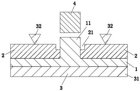
[0049] see figure 1 with figure 2 . A method for joining an amorphous alloy electronic product casing and a middle plate, comprising the following steps:

[0050] Step 1, pre-bonding: Pre-bonding the shell 1 of the amorphous alloy electronic product with the middle plate 2, wherein the shell 1 of the amorphous alloy electronic product has a convex column structure 11, and the middle plate 2 is provided with a through hole 21; the amorphous alloy electronic product The protrusion structure 11 of the product shell 1 is inserted into the through hole 21 of the middle plate 2, and locked by the clamp 3 so that the amorphous alloy electronic product shell 1 and the middle plate 2 are pre-bonded to obtain a pre-bonded whole; In this embodiment, the protrusion structure 11 is a solid cylinder; wherein, the upper part of the through hole of the middle plate 2 is provided with a chamfer structure 201;

[0051] In this embodiment, when pre-combined, the height of the protrusion stru...

Embodiment 2

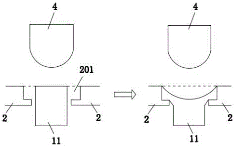
[0059] See image 3 . A method for joining an amorphous alloy electronic product casing and a middle plate, comprising the following steps:

[0060] Step 1, pre-bonding: pre-bonding the shell of the amorphous alloy electronic product with the middle plate 2, wherein the shell of the amorphous alloy electronic product has a convex column structure 11, and the middle plate 2 is provided with a through hole 21; the shell of the amorphous alloy electronic product The convex post structure 11 is inserted into the through hole 21 of the middle plate 2, and is locked by the clamp 3 so that the shell of the amorphous alloy electronic product and the middle plate 2 are pre-bonded to obtain a pre-bonded whole; in this embodiment , the convex column structure 11 is a solid cylinder; wherein, the upper part of the through hole of the middle plate 2 is provided with a chamfering structure 201;

[0061] In this embodiment, when pre-combined, the height of the protrusion structure 11 of th...

Embodiment 3

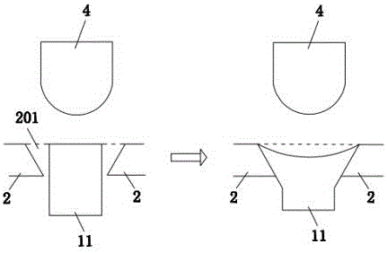
[0069] See Figure 4 . A method for joining an amorphous alloy electronic product casing and a middle plate, comprising the following steps:

[0070] Step 1, pre-bonding: pre-bonding the shell of the amorphous alloy electronic product with the middle plate 2, wherein the shell of the amorphous alloy electronic product has a convex column structure 11, and the middle plate 2 is provided with a through hole 21; the shell of the amorphous alloy electronic product The convex post structure 11 is inserted into the through hole 21 of the middle plate 2, and is locked by a clamp so that the shell of the amorphous alloy electronic product and the middle plate 2 are pre-bonded to obtain a pre-bonded whole; in this embodiment, The convex column structure 11 is a solid circular platform; wherein, the upper part of the through hole of the middle plate 2 is provided with a chamfering structure 201;

[0071] In this embodiment, when pre-combined, the height of the protrusion structure 11 ...


PUM


Abstract

The inventionrelates to the technical field of the production of an amorphous alloy product, and in particular relates to a joining method of an amorphous alloy electronic product shell and a middle plate. The method comprises the following steps: step one, pre-bonding; step two, heating; step three, pressing according to a molten-state gravity effect; and step four, cooling and sizing. By use of the joining method disclosed by the invention, a convex column structure of the amorphous alloy electronic product shell is heated to Tg and more, wherein the Tg is the glass transformationtemperature, and the heating process is controlled according to a TTT graph so as to prevent convex column structure of the amorphous alloy electronic product shell from generating the crystallization. Furthermore, a chamfer structure or a circular concave structure region can be filled with amorphous alloy in the bonding so as to form an inverted buckling structure, thereby enhancing the bonding strength performance by increasing the bonding surface in the bonding. The bonding strength of theamorphous alloy electronic product shell and the middle plate is good, and the method has the advantages of being mass in production, high in production efficiency and low in production cost.

Description

technical field [0001] The invention relates to the technical field of production of amorphous alloy products, in particular to a method for joining an outer casing and a middle plate of an amorphous alloy electronic product. Background technique [0002] Amorphous alloys have excellent mechanical properties, high chemical stability and luxurious appearance, so they have great potential in the application of 3C products. In terms of mobile phone applications, amorphous alloys are very suitable for making mobile phone casings to achieve high strength, scratch resistance, corrosion resistance, and high-quality appearance. At the same time, considering the design requirements of the shell of the amorphous alloy electronic product itself, it is necessary to combine the shell of the amorphous alloy electronic product with the middle plate. However, if an amorphous alloy is used to form the middle plate structure at the same time, after the amorphous alloy electronic product casi...

Claims


Application Information

Patent Timeline
IPC IPC(8): H05K5/00
CPCH05K5/00
Inventor 李昊度
Owner DONGGUAN PROMETAL TECH CO LTD
Why Eureka
Try Eureka