Techniques used to determine the center of the application area

A centering point and center point technology, applied in the technical field for determining the center of the application area, can solve the problems of time-consuming manual offset, uncertainty, inaccurate ablation results, etc.

Active Publication Date: 2018-12-14
ALCON INC
View PDF6 Cites 1 Cited by
  • Summary
  • Abstract
  • Description
  • Claims
  • Application Information

AI Technical Summary

Problems solved by technology

However, manually biased centering points are routinely based on subjective visual estimates and are limited by the instrumentation used for visual inspection (e.g. microscope resolution)
Additionally, the mere fact that biasing is performed manually can introduce uncertainties and lead to inaccuracies in ablation results, for example after applying drugs as well as using surgical instruments
Furthermore, manual biasing is time consuming and requires additional effort by the surgeon

Method used


Image

  • Techniques used to determine the center of the application area
  • Techniques used to determine the center of the application area
  • Techniques used to determine the center of the application area

Examples


Embodiment Construction

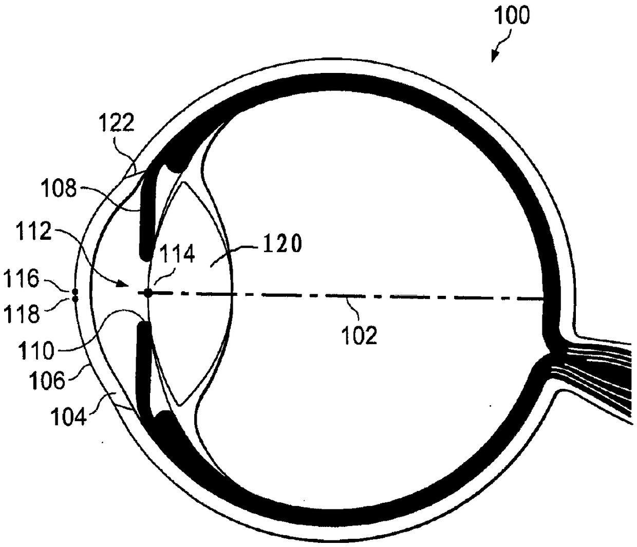
[0043] In the following description, for purposes of explanation and not limitation, specific details are set forth, such as specific device configurations and specific points on the cornea, in order to provide a thorough understanding of the techniques disclosed herein. It will be apparent to those skilled in the art that the technology may be practiced in other embodiments that depart from these specific details. For example, although the following embodiments are described with respect to the corneal apex, the technique is readily practiced using the intersection of the optic axis of the apex and the corneal surface, or the apex of the corneal surface, instead of or in conjunction with the apex.

[0044] Those skilled in the art will also appreciate that the methods, functions and components explained herein can be implemented using hardware circuits alone, using software running in conjunction with a microprocessor or general purpose computer, or a combination thereof.

[...


PUM


Abstract

The present disclosure generally relates to a technique for centering an application field for an ophthalmic device or a method. More specifically, and without limitation, the disclosure relates to a device and a method for centering an application field relative to the cornea of a human eye responsive to movement of the eye tracked in real-time during the ophthalmic application based on a pupil center. An ophthalmic device or method allows performing one or more procedures with respect to an eye of a patient, such as a surgical, therapeutic and diagnostic procedure, e.g., including and not limited to Laser-Assisted in-situ Keratomileusis (LASIK), Epi-LASIK, PRK, lenticule extraction or keratoplasty.

Description

technical field [0001] The present disclosure generally relates to techniques for determining the center of an application area for ophthalmic applications. More particularly and without limitation, the present disclosure relates to apparatus and methods for determining the center of an application region relative to the cornea of ​​a human eye in response to eye movements based on pupil center real-time tracking during ophthalmic applications. Background technique [0002] An ophthalmic device or method of operating such a device that allows one or more procedures (i.e., ophthalmic applications) to be performed on a patient's eye, such as surgical, therapeutic, or diagnostic procedures, including, for example and without limitation, LASIK (Laser In Situ Keratomileusis) ), Epi-LASIK, PRK, microlens extraction, or keratoplasty. [0003] Eye fixation can be avoided by real-time tracking of eye movements (eg, involuntary saccades) during ophthalmic applications (eg, laser abla...

Claims


Application Information

Patent Timeline
Patent Type & Authority Patents(China)
IPC IPC(8): A61B3/113A61F9/008
CPCA61B3/113A61F2009/00846A61F9/008A61B3/107A61B3/112A61B3/152A61H5/00
Inventor S·雷蒙尼斯M·阿布拉罕
Owner ALCON INC
Why Eureka
Try Eureka