Overturning device for overturning molten material and purging method

A turning device and melt technology, applied in chemical instruments and methods, fluid flow, transportation and packaging, etc., can solve the problems of time consumption, cost, waste, and inability to carry out valuable production, so as to reduce thermal impact and shorten stay Duration, avoiding delayed effects

Inactive Publication Date: 2017-05-10
WINDMOELLER & HOELSCHER GMBH
View PDF0 Cites 0 Cited by
  • Summary
  • Abstract
  • Description
  • Claims
  • Application Information

AI Technical Summary

Problems solved by technology

Therefore the scrap rate may reach a maximum of 1000kg
At the same time, the flushing time constitutes a downtime of the machine during which no valuable production can take place
Correspondingly, known extrusion devices with corresponding flushing methods are associated with clearly visible disadvantages in terms of time expenditure and corresponding costs and waste.

Method used


Image

  • Overturning device for overturning molten material and purging method
  • Overturning device for overturning molten material and purging method
  • Overturning device for overturning molten material and purging method

Examples


Embodiment Construction

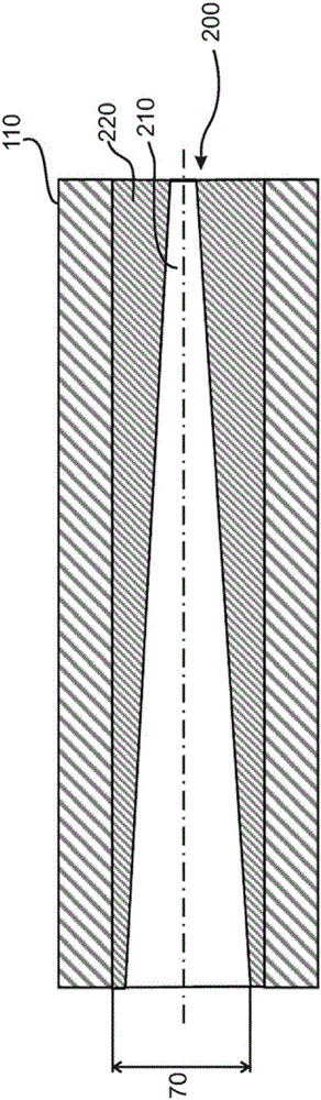
[0050] exist figure 1 The melt channel 110 with flow direction from left to right is shown in , as it appears during the flushing process. A free flow cross section 70 is provided within the melt channel 110 , through which the melt 200 flows. A distinction is made here between old melt material 220 and new melt material 210 . It can be clearly seen here that the elongated course through the melt channel 110 forms a ramp-shaped or conical configuration between the old melt material 220 and the new melt material 210 during the flushing process. The cone moves to the right in course during the purge time until eventually most of the old melt material 220 has been discharged and can be further processed with active production.

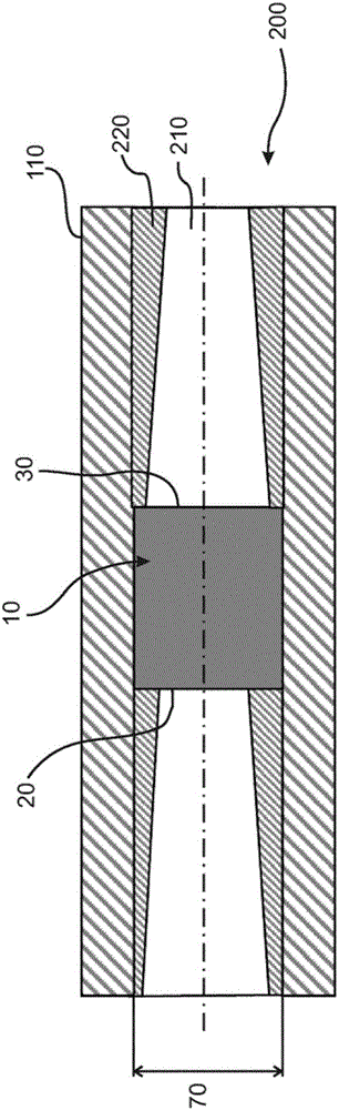
[0051] exist figure 2 The mode of operation of the turning device 10 according to the invention is shown in . Here, a transfer now takes place from the edge of the melt 200 to the center of the melt 200 and vice versa. Accordingly, material from the...


PUM


Abstract

The invention relates to an overturning device (10) for overturning molten material (200) in a melt channel (110), comprising a melt inlet (20) and a melt outlet (30), at least one melt guiding means (40) being arranged between the melt inlet (20) and the melt outlet (30) for moving molten material (200) from the center (22) of the melt inlet (20) to the edge (34) of the melt outlet (30) and for moving molten material (200) from the edge (24) of the melt inlet (20) to the center (32) of the melt outlet (30).

Description

technical field [0001] The invention relates to an inverting device for inverting a melt in a melt channel, a blow die for carrying out a blown film extrusion process and a device for carrying out a flushing process in an extrusion device method. Background technique [0002] It is known to use extrusion devices for producing plastic melts. The plastic melt can be processed further in different ways. It is thus conceivable, for example, to introduce the melt into a cavity of an injection molding device in order to produce the corresponding component there by injection molding. It is also known to provide the melt for the so-called blown extrusion process, in which blown films are extruded. In all cases, the liquefied melt must be conveyed at the end of the extruder via corresponding melt channels to the corresponding point of application. These channels can be arbitrarily complex and in particular also subdivided into individual channels. [0003] A disadvantage of the ...

Claims


Application Information

Patent Timeline
Patent Type & Authority Applications(China)
IPC IPC(8): B29C47/00B29C47/08B29C47/36B29C47/70B29B7/80B29C45/17B29C47/20B29C48/10B29C48/32
CPCB29C48/256B29C48/10B29C48/277B29C48/2692B29C48/362B29C48/27B29C48/705B29B7/802B29C45/1753B29C48/32B29C48/30B29C48/0018B29C48/70Y02P70/10F15D1/02B01F25/432B01F25/4321B01F25/4322B01F25/4323B01F25/43211B01F25/43231B29B7/325
Inventor M·巴克曼H-J·杰克艾林M·布斯曼B·利斯布罗克K·戈卢布斯基
Owner WINDMOELLER & HOELSCHER GMBH
Why Eureka
Try Eureka