Ore pulp distribution barrel and dehydration production workshop

A technology for producing workshops and distributing buckets, applied in the field of mechanical equipment, can solve problems such as unreasonable flushing and blocking angles of flushing and blocking water pipes, prolonging equipment maintenance time, increasing production energy consumption, etc., so as to reduce equipment maintenance and maintenance time, and shorten settlement time. , the effect of reducing production energy consumption

Inactive Publication Date: 2019-12-27
YUNNAN DAHONGSHAN PIPELINE
View PDF6 Cites 0 Cited by
  • Summary
  • Abstract
  • Description
  • Claims
  • Application Information

AI Technical Summary

Problems solved by technology

Before the dehydration treatment, the pulp will enter the distribution tank at the top of the dehydration production workshop for concentration ratio and overflow distribution. However, because the existing distribution tank is a standard cylinder, the overflow speed of the pulp in the distribution tank is relatively slow, and it is prone to blockage. pipe and ore accumulation
When a pipe is blocked, it is necessary to use a flushing and blocking water pipe connected to the overflow pipe to flush and block. However, the angle of the existing flushing and blocking water pipe is unreasonable, resulting in a long time for flushing and blocking. Sometimes the blocked pipe must be handled manually, and manual Unblocking will not only increase the production cost, but also bring unsafe operation of personnel in a narrow space; when ore accumulation occurs, it is necessary to start the stirring motor inside the distribution barrel
And this will increase production energy consumption, increase equipment costs and prolong equipment maintenance time

Method used


Image

  • Ore pulp distribution barrel and dehydration production workshop
  • Ore pulp distribution barrel and dehydration production workshop
  • Ore pulp distribution barrel and dehydration production workshop

Examples


Embodiment Construction

[0016] The following will clearly and completely describe the technical solutions in the embodiments of the present invention with reference to the accompanying drawings in the embodiments of the present invention. Obviously, the described embodiments are only some, not all, embodiments of the present invention. Based on the embodiments of the present invention, all other embodiments obtained by persons of ordinary skill in the art without making creative efforts belong to the protection scope of the present invention.

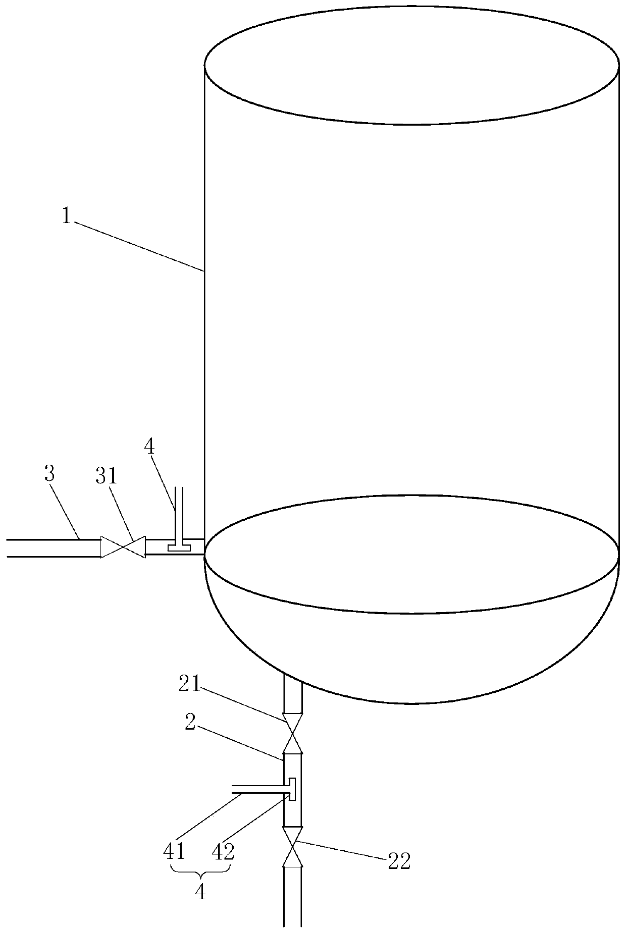
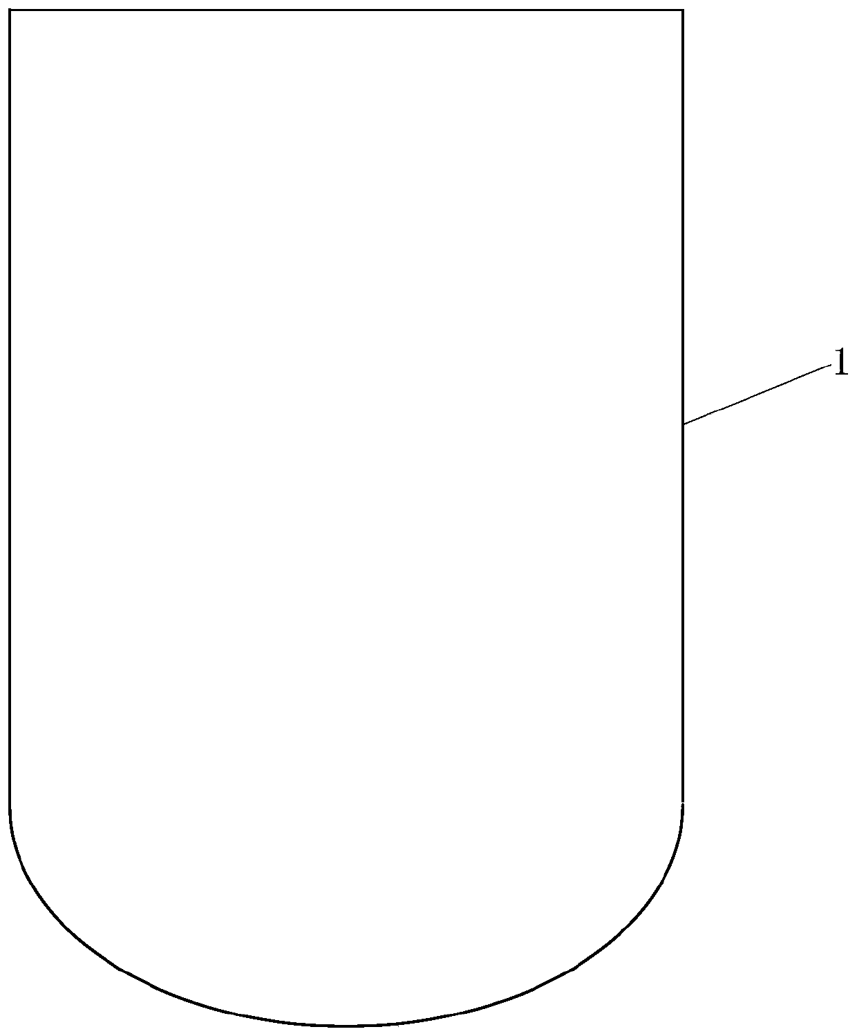
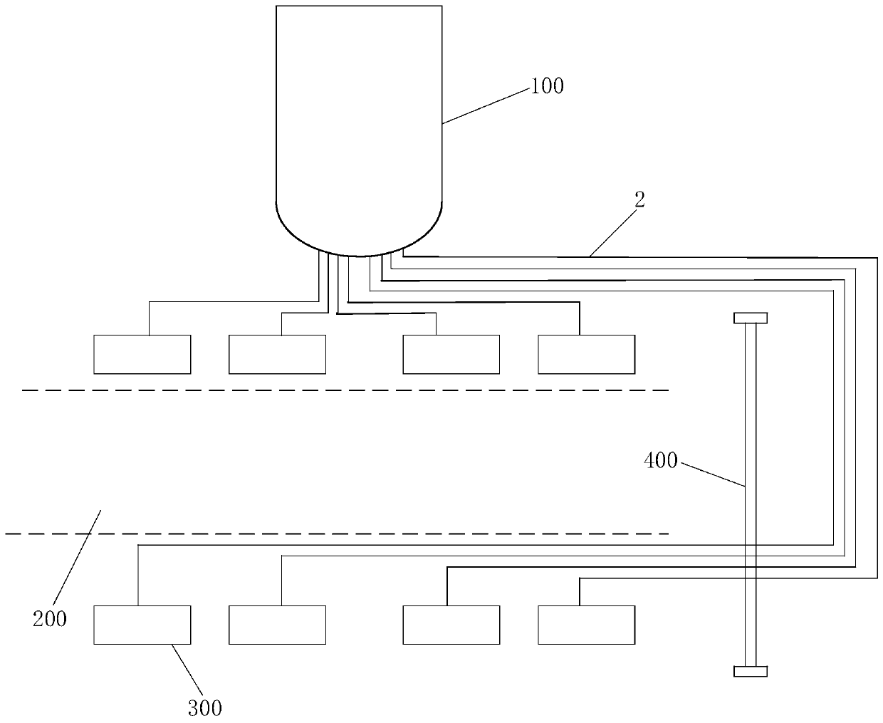
[0017] refer to figure 1 and 2 , The embodiment of the present invention provides a pulp distribution barrel. The slurry distribution barrel includes a barrel body 1, the radial cross-section of the barrel body 1 is circular, oval or square, the bottom surface of the barrel body 1 is U-shaped, and a number of overflow pipes 2 extend downward from the bottom of the barrel body 1 , the overflow pipe 2 is provided with an overflow valve 21 and a pneumatic valve...


PUM


Abstract

The invention discloses an ore pulp distribution barrel and a dehydration production workshop. The ore pulp distribution barrel comprises a barrel body, wherein the radial cross section of the barrelbody is circular, elliptical or square; the bottom surface of the barrel body is U-shaped; the bottom end of the bottom surface of the barrel body extends downwards to form a plurality of overflow pipes; an overflow valve and a pneumatic valve are arranged on each overflow pipe; the lower part of the barrel wall of the barrel body is connected with a return pipe; a return valve is arranged on thereturn pipe; flushing and blocking pipes are arranged on the overflow pipe between each overflow valve and the corresponding pneumatic valve and on the return pipe between the return valve and the barrel body; the flushing and blocking pipes comprise main water pipes perpendicularly connected with the overflow pipes or the return pipe and T-shaped three-way pipes with one end connected with the main water pipes; the T-shaped three-way pipes are located in the overflow pipes or the return pipe; and the flushing and blocking directions of the other two ends of the T-shaped three-way pipes are parallel to the overflow pipes or the return pipe. The ore pulp settling time can be effectively shortened, the ore pulp flow speed is increased, and the ore accumulation phenomenon is avoided.

Description

technical field [0001] The invention relates to the technical field of mechanical equipment, in particular to a pulp distribution barrel and a dehydration production workshop. Background technique [0002] At present, the transportation of solid materials is developing into the form of long-distance pipeline transportation, that is, solid materials such as ore and coal are ground into pulp and transported to the destination through long-distance pipelines. Before the dehydration treatment, the pulp will enter the distribution tank at the top of the dehydration production workshop for concentration ratio and overflow distribution. However, because the existing distribution tank is a standard cylinder, the overflow speed of the pulp in the distribution tank is relatively slow, and it is prone to blockage. Pipe and ore accumulation phenomenon. When a pipe is blocked, it is necessary to use a flushing and blocking water pipe connected to the overflow pipe to flush and block. Ho...

Claims


Application Information

Patent Timeline
IPC IPC(8): B01D35/00
CPCB01D35/00
Inventor 饶力李斌马波
Owner YUNNAN DAHONGSHAN PIPELINE
Why Eureka
Try Eureka