Numerical control device

A technology of numerical control devices and moving paths, which is applied in digital control, electrical program control, etc., and can solve problems such as longer moving time

Active Publication Date: 2017-05-10
MITSUBISHI ELECTRIC CORP
View PDF6 Cites 7 Cited by
  • Summary
  • Abstract
  • Description
  • Claims
  • Application Information

AI Technical Summary

Problems solved by technology

In general, when pre-interpolation acceleration and deceleration is used, excessive acceleration occurs in a path that changes rapidly, such as a corner that is a junction of each movement command. Therefore, there is a problem that each Each corner decelerates until it reaches an appropriate speed, and after passing through a corner, accelerates until it reaches the commanded feed speed, so the moving time becomes longer.

Method used


Image

  • Numerical control device
  • Numerical control device
  • Numerical control device

Examples


Embodiment approach 1

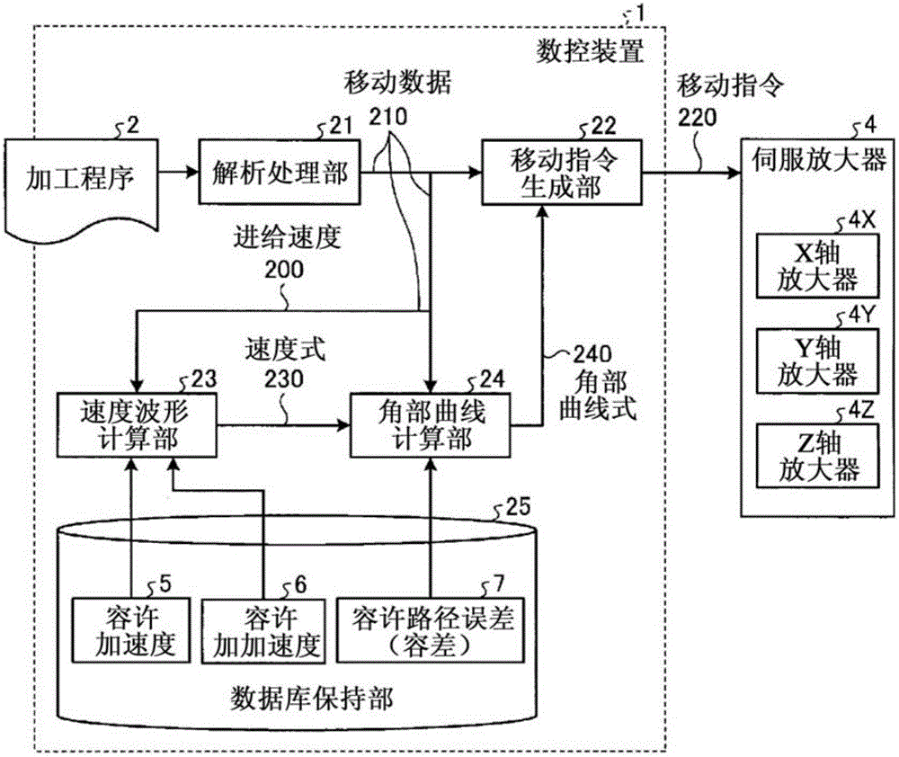
[0027] figure 1 It is a block diagram showing the configuration of the numerical control device 1 according to Embodiment 1 of the present invention. The numerical control device 1 is a device that executes numerical control (NC: Numerical Control) on a machine tool not shown.

[0028] The numerical control device 1 has an analysis processing unit 21 , a movement command generation unit 22 , a velocity waveform calculation unit 23 , a corner curve calculation unit 24 , and a database holding unit 25 . The machine tool equipped with the numerical control device 1 controls each travel axis so as to move to the position commanded by the machining program 2, that is, the NC machining program, thereby moving the table or the tool, which is a movable part on which a workpiece can be placed. , thereby controlling the positional relationship between the workpiece and the tool on the table, thereby performing machining on the workpiece.

[0029] The numerical control device 1 perform...

Embodiment approach 2

[0138] Next, the numerical control device 1 according to Embodiment 2 will be described. The structure and figure 1 same. Hereinafter, the description will focus on the differences from Embodiment 1. FIG.

[0139] In the numerical control device 1 according to the first embodiment, in the movement command generation unit 22, a method of smoothing the speed of each axis is used by replacing the movement path described in the machining program 2 with a path including corner curves. . On the other hand, the configuration of the movement command generation unit 22 of the numerical control device 1 according to the second embodiment is different from the configuration of the movement command generation unit 22 of the first embodiment. In the movement command generating unit 22 according to the second embodiment, a method is used in which the speed waveforms of the respective axes are smoothed by providing a plurality of constituent elements that perform interpolation processing....


PUM


Abstract

This numerical control device (1) for a machine tool, which controls the positional relationship between a workpiece on a table and a tool by moving the table or the tool along a plurality of translation axes, is provided with the following: an analysis processing unit (21) that outputs a movement path and a feed speed along said movement path on the basis of a machining program that contains a plurality of command blocks; a speed-waveform calculation unit (23) that calculates a speed waveform between a stationary state and a state corresponding to the aforementioned feed speed on the basis of said feed speed and preset acceleration and jerk limits; a corner-curve calculation unit (24) that calculates curve equations for corner curves obtained by smoothing the abovementioned movement path at the boundaries between the abovementioned command blocks on the basis of a preset path-error limit, the movement path, and the aforementioned speed waveform; and a movement-command generation unit (22) that outputs a movement command for each translation axis on the basis of the movement path and the aforementioned curve equations.

Description

technical field [0001] The present invention relates to a numerical control device capable of smoothing a moving path in pre-interpolation acceleration and deceleration control. Background technique [0002] In a machine tool equipped with a numerical control device, each drive shaft is controlled so as to move to a position commanded in a machining program, and machining is performed while moving a movable part. In the numerical control device, there is pre-interpolation acceleration and deceleration as a technique for accurately moving at a commanded speed along a movement path written in a machining program. Acceleration and deceleration before interpolation is a technique of generating an acceleration and deceleration waveform in the direction along the movement path, that is, a tangential direction, and performing interpolation while matching the generated acceleration and deceleration waveform to the movement path. In general, when pre-interpolation acceleration and d...

Claims


Application Information

Patent Timeline
Patent Type & Authority Applications(China)
IPC IPC(8): G05B19/416G05B19/4103
CPCG05B19/4103G05B19/416
Inventor 津田刚志大熊贤治
Owner MITSUBISHI ELECTRIC CORP
Why Eureka
Try Eureka