digital filter
A digital filter and data technology, applied in the field of digital filters, can solve problems such as the burden on users of additional detection circuits, and achieve the effect of reducing circuit scale
- Summary
- Abstract
- Description
- Claims
- Application Information
AI Technical Summary
Problems solved by technology
Method used
Image

Examples
no. 1 Embodiment
[0034] Embodiments of the present invention will be described below with reference to the drawings. image 3 It is a block diagram showing the configuration of the digital filter of the first embodiment of the present invention. The digital filter of the present embodiment includes: a multi-stage cascaded cumulative calculation unit 10, which is input at the same sampling frequency f as the sampling frequency of the data input to the digital filter. S The clock operates, and the input data is accumulated for each sample; the multi-stage cascade configuration or one-stage difference calculation part 11, which is based on the sampling frequency f D =f S The clock of / N operates, subtracting the data before 1 sample from the input data; the frequency conversion part 12 is arranged between the output of the accumulation calculation part 10 of the last stage and the input of the difference calculation part 11 of the primary stage, at sampling frequency f D Thinning out the sampl...
no. 2 Embodiment
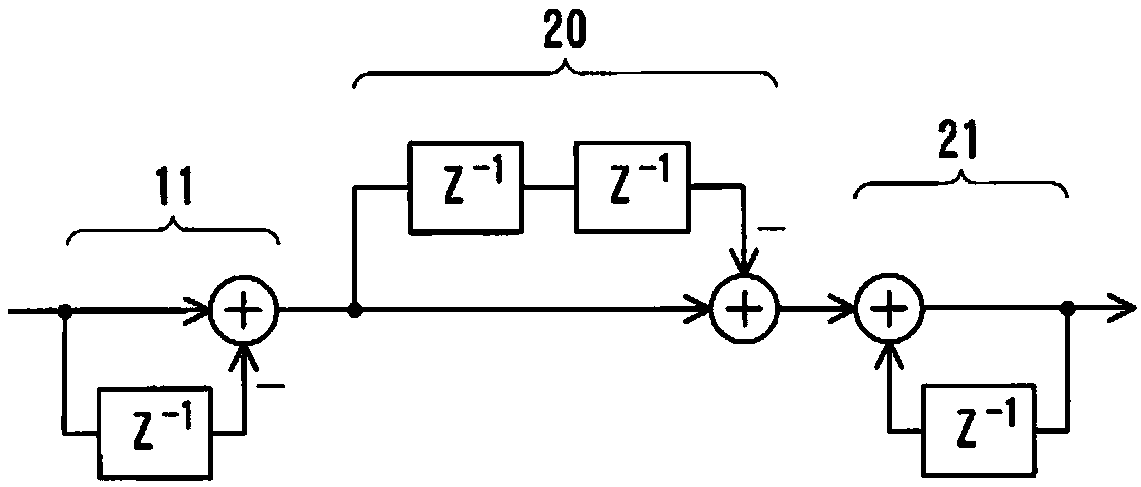
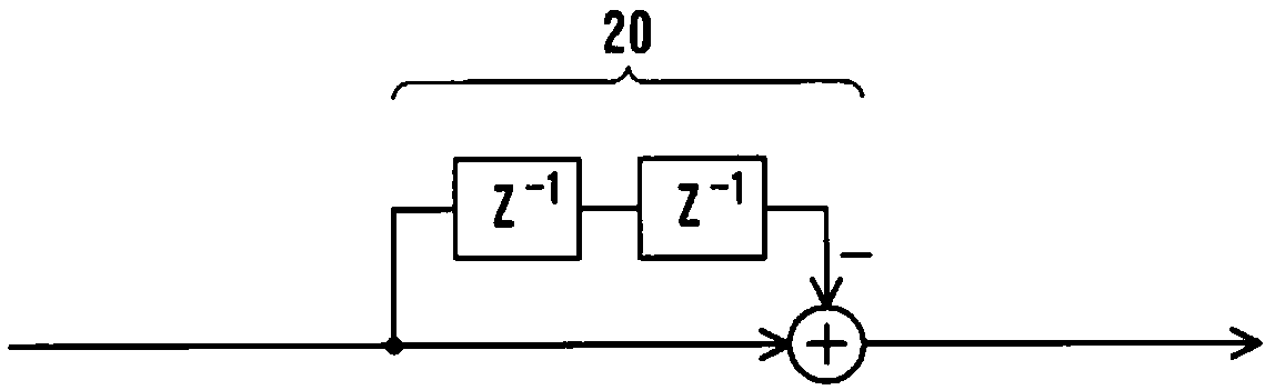
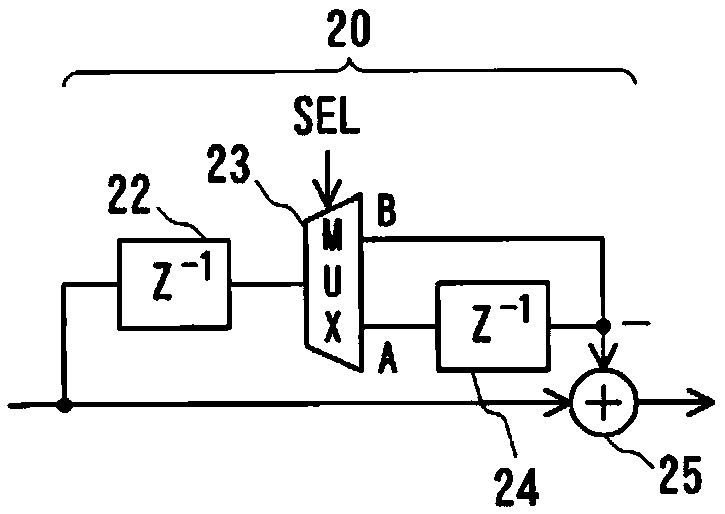
[0049] Next, a second embodiment of the present invention will be described. In the digital filter of the first embodiment, the final-stage cumulative calculation unit 10, frequency conversion unit 12, and difference calculation unit 11 are configured ( Figure 4A ) can be converted to Figure 4B looks like , which can eventually be transformed into Figure 4C look. By using the principle of this conversion, the digital filter of the first embodiment can be simplified as Figure 5 look.
[0050] In this embodiment, the cumulative calculation and frequency conversion unit 17 is used instead of image 3 The accumulation calculation unit 10 , the frequency conversion unit 12 and the difference calculation unit 11 are the final stage. In the case of providing multi-stage cascade-structured difference calculation unit 11 , an accumulation calculation and frequency conversion unit 17 may be provided instead of the last-stage accumulation calculation unit 10 , frequency conversi...
PUM
 Abstract
Description
Claims
Application Information
 - R&D
- Intellectual Property
- Life Sciences
- Materials
- Tech Scout
- Unparalleled Data Quality
- Higher Quality Content
- 60% Fewer Hallucinations
Browse by: Latest US Patents, China's latest patents, Technical Efficacy Thesaurus, Application Domain, Technology Topic, Popular Technical Reports.
© 2025 PatSnap. All rights reserved.Legal|Privacy policy|Modern Slavery Act Transparency Statement|Sitemap|About US| Contact US: help@patsnap.com