Grinding tool correction mechanism driven by servo motor

A technology of servo motor and abrasive tool, which is applied in the direction of grinding machine parts, workpiece feed movement control, and manufacturing tools, etc., can solve the problems of reducing machining accuracy, abrasive tool loss, and different widths, and improve work efficiency. , The effect of reducing production costs and simplifying process steps

Active Publication Date: 2017-05-17
HARBIN ZHANDA ROBOT AUTOMATION CO LTD
View PDF7 Cites 0 Cited by
  • Summary
  • Abstract
  • Description
  • Claims
  • Application Information

AI Technical Summary

Problems solved by technology

[0003] During the use of abrasive tools, the abrasive tools will continue to wear and tear, and the phenomenon of uneven thickness and width of the abrasive tools often occurs, which greatly reduces the processing accuracy and also affects the continued use of the abrasive tools.
At present, most of the grinding work of grinding wheels and other molds is carried out manually. Not only the labor cost is high, but also the production efficiency is relatively low, and the size and shape of the grinding tools are inconsistent.

Method used


Image

  • Grinding tool correction mechanism driven by servo motor
  • Grinding tool correction mechanism driven by servo motor
  • Grinding tool correction mechanism driven by servo motor

Examples


Embodiment 1

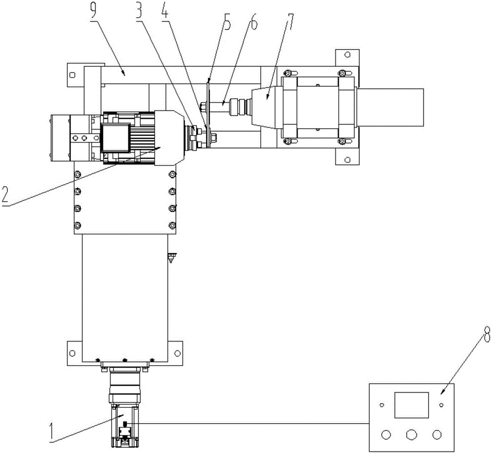
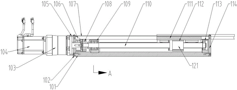
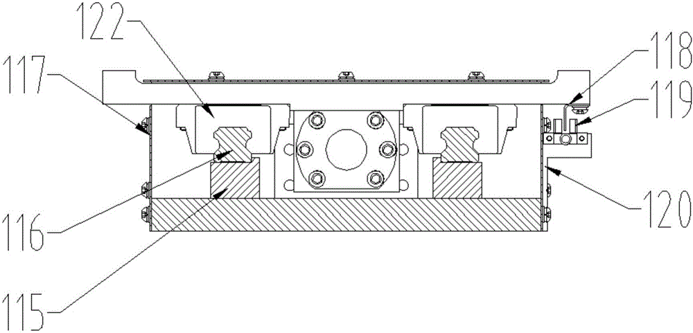
[0025] figure 1 It is a top view structural schematic diagram of a grinding tool correction device in a preferred solution of the present invention. figure 2 It is a partial cross-sectional structural schematic diagram of the front view of the two-way correction module of the abrasive tool. image 3 for figure 2 Schematic diagram of a partial cross-sectional structure along the A direction. From figure 1 It can be seen from the figure that the abrasive tool correction mechanism is mainly composed of a two-way abrasive tool correction module 1, a power device 2, a mounting flange 3, an abrasive tool grinding wheel 4, a servo controller 8 and a frame body 9. Among them, the two-way correction module 1 of the abrasive tool includes a large installation plate 101, an end vertical plate 102, a reducer 103, a servo motor 104, a servo motor mounting plate 105, a triangular rib plate 106, an upper cover plate 107, an elastic coupling 108, Ball screw 110, slider connecting plate ...

Embodiment 2

[0032] figure 2 It is a top structural schematic diagram of the mold correction device in another preferred solution of the present invention. The difference between this embodiment and embodiment 1 is that the mold used is a grinding rod, and the grinding machine 7 is a grinding rod machine. Abrasive grinding wheel 4 is a grinding rod grinding wheel. At the same time, the length direction of the support 9 is the same as the length direction of the grinding tool bidirectional correction module 1 (the two directions are perpendicular in Embodiment 1). Simultaneously, the grinding tool installation shaft 6 is not provided, and the grinding tool 5, that is, the grinding rod, is directly installed on the grinding tool machine 7 (ie, the grinding rod machine 7).


PUM


Abstract

The invention discloses a grinding tool correction mechanism driven by a servo motor and belongs to the technical field of machining. The grinding tool correction mechanism comprises a grinding tool bidirectional correction mold group, a power device installed on the grinding tool bidirectional correction mold group, a grinding tool grinding wheel which is connected with a power output device of the power device and a servo controller which is electrically connected with the grinding tool bidirectional correction mold group, wherein the grinding tool bidirectional correction mold group is composed of a servo motor, a ball screw which is connected with a servo motor output shaft through a reducer and an elastic coupling and a sliding block connecting plate which is connected with a screw nut on the ball screw; the power device is fixed on the sliding block connecting plate; and a photoelectric sensor used for detecting a movement journey of the ball screw is also arranged on the side surface of the ball screw. According to the grinding tool correction mechanism, the bidirectional correction mold group is driven to move by the servo motor to correct a grinding tool with high accuracy, the appearance size, subjected to correction, of the grinding tool is fed back and output to be supplied for other external systems to use, and larger automation degree of a polishing operation system can be realized.

Description

technical field [0001] The invention relates to a grinding tool correction mechanism driven by a servo motor, which belongs to the technical field of mechanical processing. Background technique [0002] Abrasives are tools used in grinding, grinding and polishing processes. They are not only widely used in machinery manufacturing and metal processing, but also in grain processing, paper industry, ceramics, glass, stone, plastic, rubber and Wood and other non-metallic materials processing field. Most of the existing grinding tools are artificial grinding tools made of abrasives and bonding agents, but there are also natural grinding tools that are directly processed from natural ore rocks. [0003] During the use of the abrasive tool, the abrasive tool will be continuously worn out, and the phenomenon of uneven thickness and uneven width of the abrasive tool often occurs, which greatly reduces the processing accuracy and also affects the continued use of the abrasive tool. ...

Claims


Application Information

Patent Timeline
Patent Type & Authority Applications(China)
IPC IPC(8): B24B53/06B24B49/00
CPCB24B49/00B24B53/06
Inventor 刘广利蔡宇祥李海东张大明
Owner HARBIN ZHANDA ROBOT AUTOMATION CO LTD
Why Eureka
Try Eureka