Adjustable air compressing device for quenching cold air grate of glass toughening furnace

A glass tempering and adjustable technology, used in glass tempering, glass manufacturing equipment, manufacturing tools, etc., can solve the problems of glass deformation, fast cooling, uneven glass cooling, etc., to prevent glass deformation, improve the tempering effect, Anti-deformation effect is remarkable

Active Publication Date: 2017-05-17
SOOS (GUANGDONG) GLASS TECH CO LTD
View PDF5 Cites 3 Cited by
  • Summary
  • Abstract
  • Description
  • Claims
  • Application Information

AI Technical Summary

Problems solved by technology

[0005] Although the space between two adjacent upwind grilles 1a is blocked by the windshield 3a to slow down the flow, but for the two ends of the upper wind grilles 1a perpendicular to the direction of glass movement, the space is still relatively open, so that the space at this position The air fluidity will be better than the air fluidity in other parts, which will cause the cooling speed of the two ends of the upper surface of the glass in the width direction to be fast, while the cooling speed of the middle part will be slow, making the cooling of the glass uneven, which will affect the tempering quality of the glass, especially Will cause the tempered glass to deform
The reason is that the edge of the glass is cooled and shaped first, and the middle part is cooled and shaped later, so that the middle part of the glass is easy to bulge upwards or sag downwards relative to the edge under the action of external forces (such as vibration, gravity, etc.), resulting in The flatness of glass is difficult to meet the use standard, especially for mirror glass with a thickness of less than 1mm, the existing production process is difficult to meet the use requirements

Method used


Image

  • Adjustable air compressing device for quenching cold air grate of glass toughening furnace
  • Adjustable air compressing device for quenching cold air grate of glass toughening furnace
  • Adjustable air compressing device for quenching cold air grate of glass toughening furnace

Examples


Embodiment 1

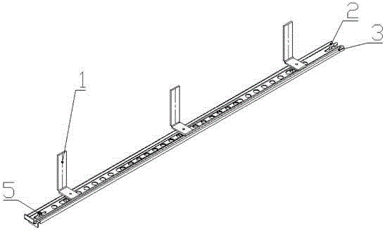
[0031] see Figure 3 ~ Figure 5 , the adjustable air pressure device for the quenching air grid of the glass tempering furnace of the present invention includes a mounting plate 1 and a pressure air mechanism, the air pressure mechanism is connected to the mounting plate 1, and the mounting plate 1 is connected to the air grid; wherein :

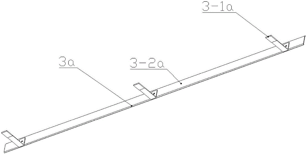
[0032] The air pressure mechanism includes an air pressure plate 3 and a first adjustment plate 2 stacked together. The plates 2 are connected together by an adjustable connection structure 5 that can move relatively in the length direction; the air pressure plate 3 is arranged with a plurality of first ventilation holes 3-3 along the length direction; the middle part of the first adjustment plate 2 There are first long ventilation holes 2-4, and first adjustment holes 2-3 are arranged at both ends.

[0033] see Figure 3 ~ Figure 6 , the adjustable connection structure includes a first connection slot 2-1 extending along the length direc...

Embodiment 2

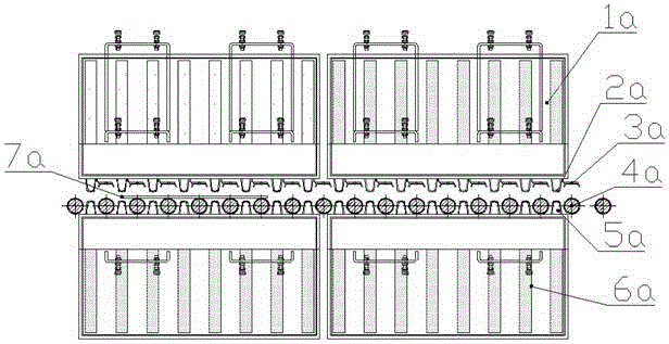
[0038] see Figure 7 The difference between this embodiment and embodiment 1 is that the air pressure mechanism also includes a second adjustment plate 4; the second adjustment plate 4 is installed on the lower side of the first adjustment plate 2, and the first adjustment plate 2 Located on the upper side of the air pressure plate 3; the middle part of the second adjustment plate 4 is provided with a second adjustment hole 4-3 arranged along the length direction, and the arrangement spacing of the second adjustment holes 4-3 is the same as that on the air pressure plate 3. The first ventilation holes 3-3 are consistent with each other, and the two ends of the second adjusting plate 4 are provided with second adjusting long holes 4-4 extending along the length direction. The purpose of adopting the above structure is to adjust the ventilation volume in the middle of the air pressure mechanism, specifically, similar to the adjustment principle between the first adjustment plate...

Embodiment 3

[0042] see Figure 8 The difference between this embodiment and Embodiment 1 is that the air pressure mechanism also includes a third adjustment plate 6; the third adjustment plate 6 is installed on the lower side of the first adjustment plate 2, and the first adjustment plate 2 Located on the upper side of the air pressure plate 3; the third adjustment plate is provided with third adjustment holes 6-1 arranged along the length direction, and the arrangement spacing of the third adjustment holes 6-1 is the same as that of the first air pressure plate 3 A ventilation hole 3-3 is consistent. The purpose of adopting the above-mentioned structure is to uniformly adjust the ventilation volume on the entire length range of the air pressure mechanism. Specifically, by adjusting the positional relationship between the third adjustment plate 6 and the air pressure plate 3, the air pressure on the air pressure plate 3 can be changed. The degree of coincidence between all the first vent...


PUM

PropertyMeasurementUnit
thicknessaaaaaaaaaa

Abstract

The invention discloses an adjustable air compressing device for a quenching cold air grate of a glass toughening furnace. The adjustable air compressing device comprises a mounting plate and an air compressing mechanism, wherein the air compressing mechanism is connected with the mounting plate; the mounting plate is connected with an air grate; the air compressing mechanism comprises an air compressing plate and a first adjusting plate which are overlapped with each other; the air compressing plate and the first adjusting plate are connected through an adjustable connecting structure; the tightness of the adjustable connecting structure can be adjusted; the adjustable connecting structure can drive the air compressing plate and the first adjusting plate to relatively move along a length direction; a plurality of first air vents are arrayed on the air compressing plate along the length direction; a first long ventilating hole is formed in the middle of the first adjusting plate; first adjusting holes are formed at the two ends of the first adjusting plate; the arraying distance of the first adjusting holes is consistent to the arraying distance of the first air vents on the air compressing plate. Under the effect of the adjustable air compressing device disclosed by the invention, the upper surface of the processed glass can be uniformly cooled and the glass deformation is prevented, so that the glass quality is increased.

Description

technical field [0001] The invention relates to a glass tempering furnace, in particular to an adjustable air pressure device for the quenching air grid of the glass tempering furnace. Background technique [0002] Such as figure 1 As shown, the wind deflector 3a is also called the air pressure plate, and it is arranged between two adjacent upper air grid strips 2a of the quenching air grid in the production line of the glass tempering furnace. When the glass 7a heated to a certain temperature enters the quenching air grid under the drive of the transmission roller, the wind with a certain pressure and flow entering the upper wind grid bar 1a and the lower wind grid bar 6a passes through the wind from the upper wind grid hole 2a and the lower wind grid hole 5a. The mouth blows to the top and bottom of the glass 7a at the same time, and there is a certain rebound after the wind blows to the surface of the glass 7a. The wind blowing to the glass from the lower wind grid bar 6...

Claims


Application Information

Patent Timeline
Patent Type & Authority Applications(China)
IPC IPC(8): C03B27/04
CPCC03B27/04
Inventor 周军山
Owner SOOS (GUANGDONG) GLASS TECH CO LTD
Why Eureka
Try Eureka