
Connection joint of box-shaped steel beam and concrete filled steel tubular column and construction method of connection joint

A technology of concrete-filled steel tubular columns and box-shaped steel beams, which is applied in the direction of buildings, building structures, etc.

Active Publication Date: 2017-05-17
ARCHITECTURAL DESIGN RES INST OF GUANGDONG PROVINCE
View PDF6 Cites 0 Cited by
  • Summary
  • Abstract
  • Description
  • Claims
  • Application Information

AI Technical Summary

Problems solved by technology

[0007] The technical problem to be solved by the present invention is to provide a connection node between a box-shaped steel beam and a concrete-filled steel tube column and its construction method, so as to overcome the problems in the prior art During the construction of the connection joint between the box-shaped steel beam and the concrete-filled steel tube column, it is necessary to open holes on the flange of the box-shaped steel beam to put in the connecting bolts

Method used


Image

  • Connection joint of box-shaped steel beam and concrete filled steel tubular column and construction method of connection joint
  • Connection joint of box-shaped steel beam and concrete filled steel tubular column and construction method of connection joint
  • Connection joint of box-shaped steel beam and concrete filled steel tubular column and construction method of connection joint

Examples


Embodiment 1

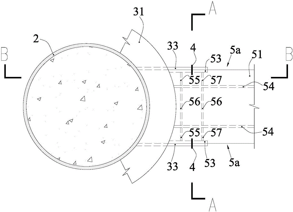
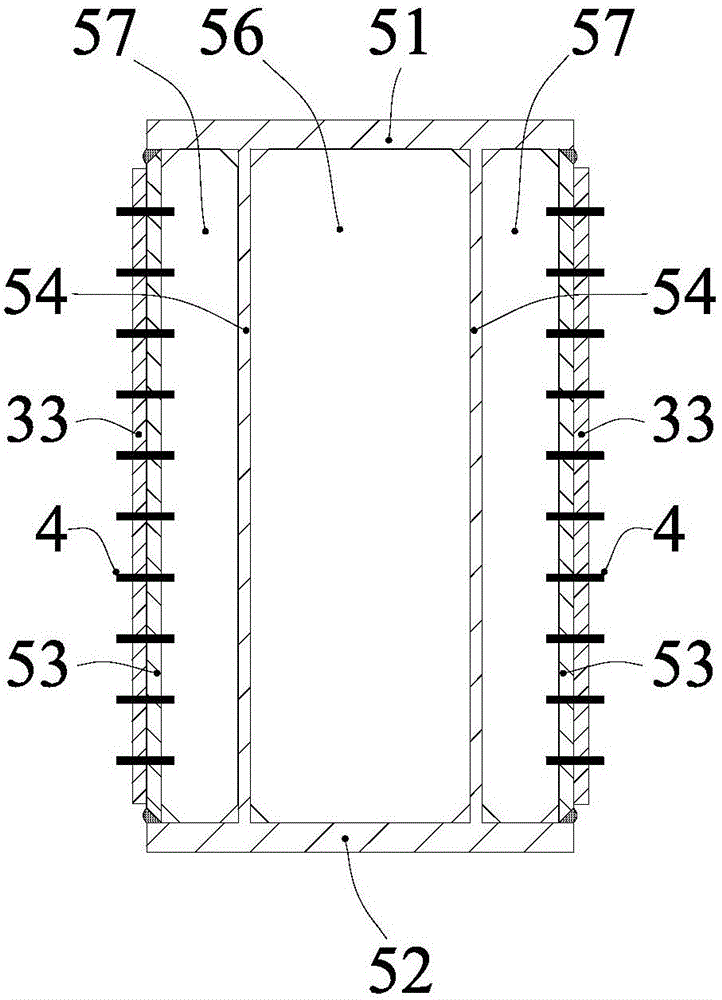
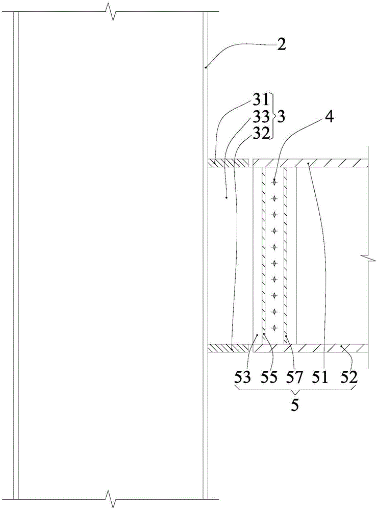
[0084] Such as Figure 6 to Figure 9 As shown, Embodiment 1 of the present invention is based on the above-mentioned general inventive concept, and adopts the following specific schemes for the manner of forming the shear force transfer structure 5:

[0085] The box-shaped steel girder 1 is a first-form box-shaped steel girder 1A, and the two beam webs 13A of the first-form box-shaped steel girder 1A are connected to the middle of the bottom surface of the beam upper flange 11A and the top of the beam lower flange 12A. Between the middle of the surface, that is, the two side edges 111A of the beam upper flange 11A of the first form of box-shaped steel girder 1A and the two side edges 121A of the beam lower flange 12A respectively extend to the two sides of the first form of box-shaped steel girder 1A. outside of the block beam web 13A.

[0086] The beam force transmission member 6 is an outsourcing beam force transmission component, which is composed of two outer force transm...

Embodiment 2

[0090] Such as Figure 10 to Figure 13 As shown, the second embodiment of the present invention is based on the above-mentioned general inventive concept, and adopts the following specific schemes for forming the shear force transfer structure 5:

[0091] The box-shaped steel girder 1 is a second-form box-shaped steel girder 1B, and the edges of the beam upper flange 11B, the beam lower flange 12B and the two beam webs 13B of the second-form box-shaped steel girder 1B are flush, that is, the second The box-shaped steel girder 1B of the first form has a "mouth" cross-section; and the beam web 13B of the second-form box-shaped steel beam 1B is provided with an installation through hole 13a close to the end of the second-form box-shaped steel beam 1B.

[0092] Beam force transmission member 6 is an embedded beam force transmission member, which is composed of two inner force transmission webs 61B, two front front force transmission transverse ribs 62B, two front middle force tran...

Embodiment 3

[0098] Such as Figure 14 As shown, the third embodiment of the present invention is based on the above-mentioned general inventive concept, and adopts the following specific scheme to realize the simultaneous connection of the steel-filled steel tube column 2 with multiple box-shaped steel beams 1 and improve the connection strength between the box-shaped steel beam 1 and the steel-filled steel tube column 2 :

[0099] The connection node of the third embodiment of the present invention is provided with at least two box-shaped steel beams 1, and the upper column force transmission flange 31 and the lower column force transmission flange 32 of the column force transmission member 3 are ring plates, and the ring plates pass through their The central through hole is set outside the steel tube concrete column 2 and connected with the steel tube concrete column 2 by surrounding welding. The column force transmission member 3 is equipped with two column force transmission webs 33 c...


PUM


Abstract

The invention discloses a connection joint of a box-shaped steel beam and a concrete filled steel tubular column and a construction method of the connection joint. The connection joint is composed of the box-shaped steel beam, the concrete filled steel tubular column and a force transferring assembly. The force transferring assembly comprises a force transferring component, a beam force transferring component and a bolt and nut locking suite. The end of the box-shaped steel beam and the beam force transferring component form a shearing force transferring structure. The shearing force transferring structure is composed of an upper flange, a lower flange, two outer webs, two inner webs, two front cross rib plates, two middle cross rib plates and two rear cross rib plates. Damage to the structural integrity of the flanges of the box-shaped steel beam due to tapping does not affect the bending moment transferring effect or weaken the connection joint, so that the connection joint is more reliable in quality, clearer in force transferring and more uniform in stress. Bolts of the bolt and nut locking suite are put into installation openings without tapping in the construction method of the connection joint, so that the connection joint is easier and more convenient to construct and higher in operability.

Description

technical field [0001] The invention relates to a connection node between a box-shaped steel beam and a steel tube concrete column, and a construction method for the connection node. Background technique [0002] The box section, like the H section, is an ideal section for beam members mainly resistant to bending and shearing. Compared with the H section, the box section has better axial and torsional resistance; Due to its high strength and good seismic performance, it has been widely used in high-rise and super high-rise building structures. [0003] The connection between the steel beam and the steel pipe concrete column is the key to the engineering design and construction. The joint structure generally adopts the combination of bolt and welding, that is, the flange of the steel beam and the ring plate of the steel pipe column are welded, and the web and the steel pipe column are connected by bolts on the connecting plate. , which has the advantages of high safety, high...

Claims


Application Information

Patent Timeline
Patent Type & Authority Applications(China)
IPC IPC(8): E04B1/18E04B1/58
CPCE04B1/185
Inventor 张立平陈星徐卫陈剑易静仪王元德王昱涵
Owner ARCHITECTURAL DESIGN RES INST OF GUANGDONG PROVINCE
Learn More